Planetary ball mill
The technology of a planetary ball mill and a ball mill can be applied to grain processing and other directions, which can solve the problems of changing the ratio of the friction effect and impact effect of the grinding ball and the abrasive, the effect of the impact effect is not obvious, and changing, so as to increase the impact force, It is beneficial to the mechanical alloying of abrasives and the effect of improving the efficiency of ball milling
- Summary
- Abstract
- Description
- Claims
- Application Information
AI Technical Summary
Problems solved by technology
Method used
Image
Examples
Embodiment 1
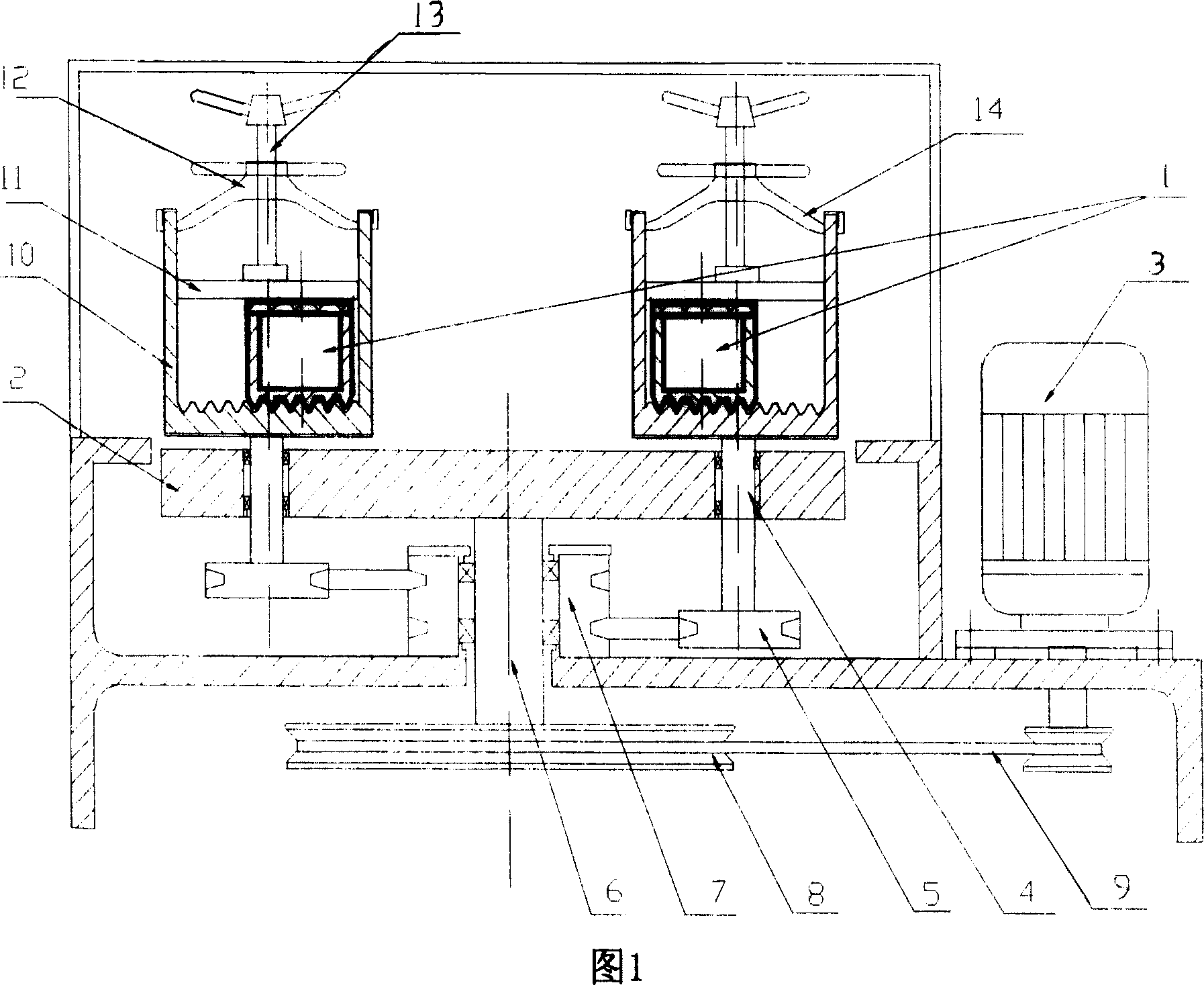
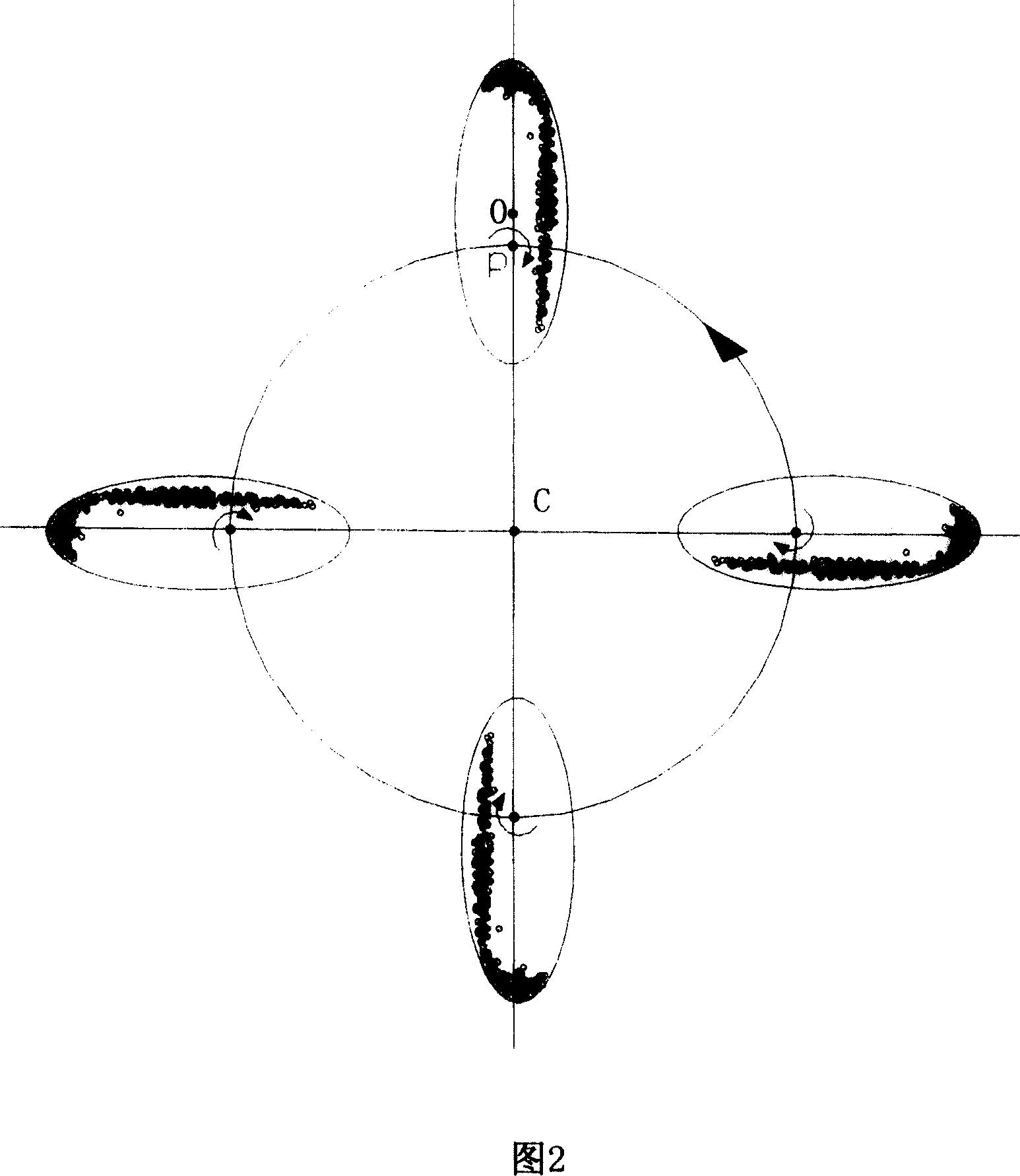
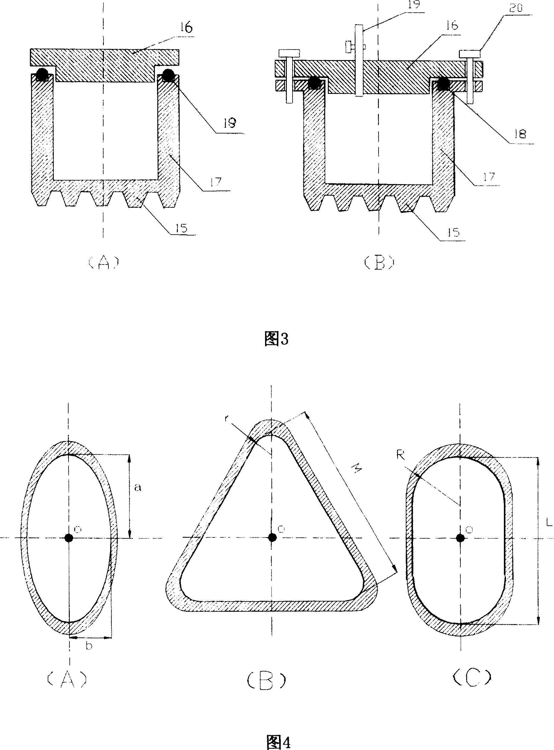
[0022] As shown in Figures 1, 2, and 3 (A), this planetary ball mill includes a ball mill pot 1, a turntable 2, a transmission gear set, and a drive motor 3. The ball mill pot 1 is connected to the turntable 2 and the drive gear set through the rotation shaft 4 respectively The driven gear 5 is connected, and the turntable 2 is connected with the driving gear 7 of the transmission gear set through the revolution shaft 6. The center line is parallel to the geometric center line of the ball mill jar 1 cross section.
[0023] The tops of the respective rotating shafts are fixedly connected with a ball milling pot fastening device, and each ball milling pot fastening device includes a base 10, a gland 11 and a claw 12; The tank 1 is placed in the cup cavity of the base 10; the gland 11 is located above the ball milling tank 1 in the cup-shaped base 10, and there is a screw 13 on the upper side of the gland 11; the middle part of the claw 12 is a screw 13 on the gland 11 For the m...
Embodiment 2
[0029] The structure of the planetary ball mill is the same as in Embodiment 1, wherein the cross-sectional shape of the ball mill tank 1 is shown in Figure 4(A). The cross-section of the ball mill tank of this planetary ball mill is elliptical, with a minor semi-axis b and a major semi-axis a. When b / a=1, the grinding effect is the largest and the impact effect is the smallest; when b / a<1 and the value becomes smaller , the friction effect is reduced, and the impact effect is increased. In order to achieve a better ratio of friction force to impact force, the preferred range of the ratio of the minor semi-axis b to the major semi-axis a of the ellipse is: 0.2≤b / a<1.
Embodiment 3
[0031] The structure of the planetary ball mill is the same as in Embodiment 1, wherein the cross-sectional shape of the ball mill tank 1 is shown in Figure 4(B). The cross-section of the ball mill tank of this planetary ball mill is an equilateral triangle with rounded transitions between adjacent sides, the radius of the rounded corner is r, and the length of the side is M. When r / M becomes smaller, the friction effect decreases and the impact effect increases. In order to achieve a better ratio of friction force to impact force, the preferred range of the ratio of the fillet radius r to the side length M is: 0.05≤r / M≤0.28.
PUM
 Abstract
Description
Claims
Application Information
 - R&D
- Intellectual Property
- Life Sciences
- Materials
- Tech Scout
- Unparalleled Data Quality
- Higher Quality Content
- 60% Fewer Hallucinations
Browse by: Latest US Patents, China's latest patents, Technical Efficacy Thesaurus, Application Domain, Technology Topic, Popular Technical Reports.
© 2025 PatSnap. All rights reserved.Legal|Privacy policy|Modern Slavery Act Transparency Statement|Sitemap|About US| Contact US: help@patsnap.com


