Cutting mechanism of rod material automatic cutting machine

A cutting mechanism and cutting machine technology, applied in the field of automatic bar cutting machine and cutting mechanism of the automatic bar cutting machine, can solve the problems of low precision, inconsistent cutting length, easy tilting of the bar, and achieve reliable operation and structure. Simple and reasonable effect

Inactive Publication Date: 2008-06-11
玉环县三合机床厂(普通合伙)
View PDF8 Cites 3 Cited by
  • Summary
  • Abstract
  • Description
  • Claims
  • Application Information

AI Technical Summary

Problems solved by technology

However, the cutting machine uses the cylinder to control the blade to move up and down to cut the bar. Although the cylinder pushes the piston rod to move up and down, although the speed is fast, there are problems of low precision and complicated equipment structure.
[0004] In addition, there is no mechanism to support the bar at the cutting point, and the bar is easy to tilt, resulting in irregular cuts and inconsistent cutting lengths

Method used


Image

  • Cutting mechanism of rod material automatic cutting machine
  • Cutting mechanism of rod material automatic cutting machine
  • Cutting mechanism of rod material automatic cutting machine

Examples


Embodiment Construction

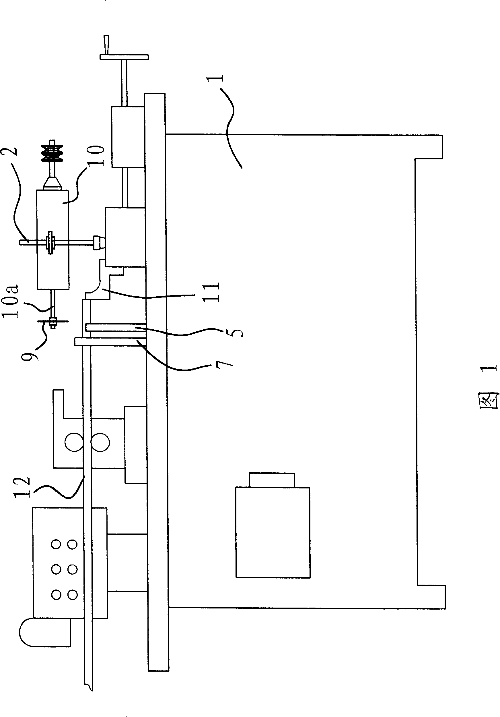
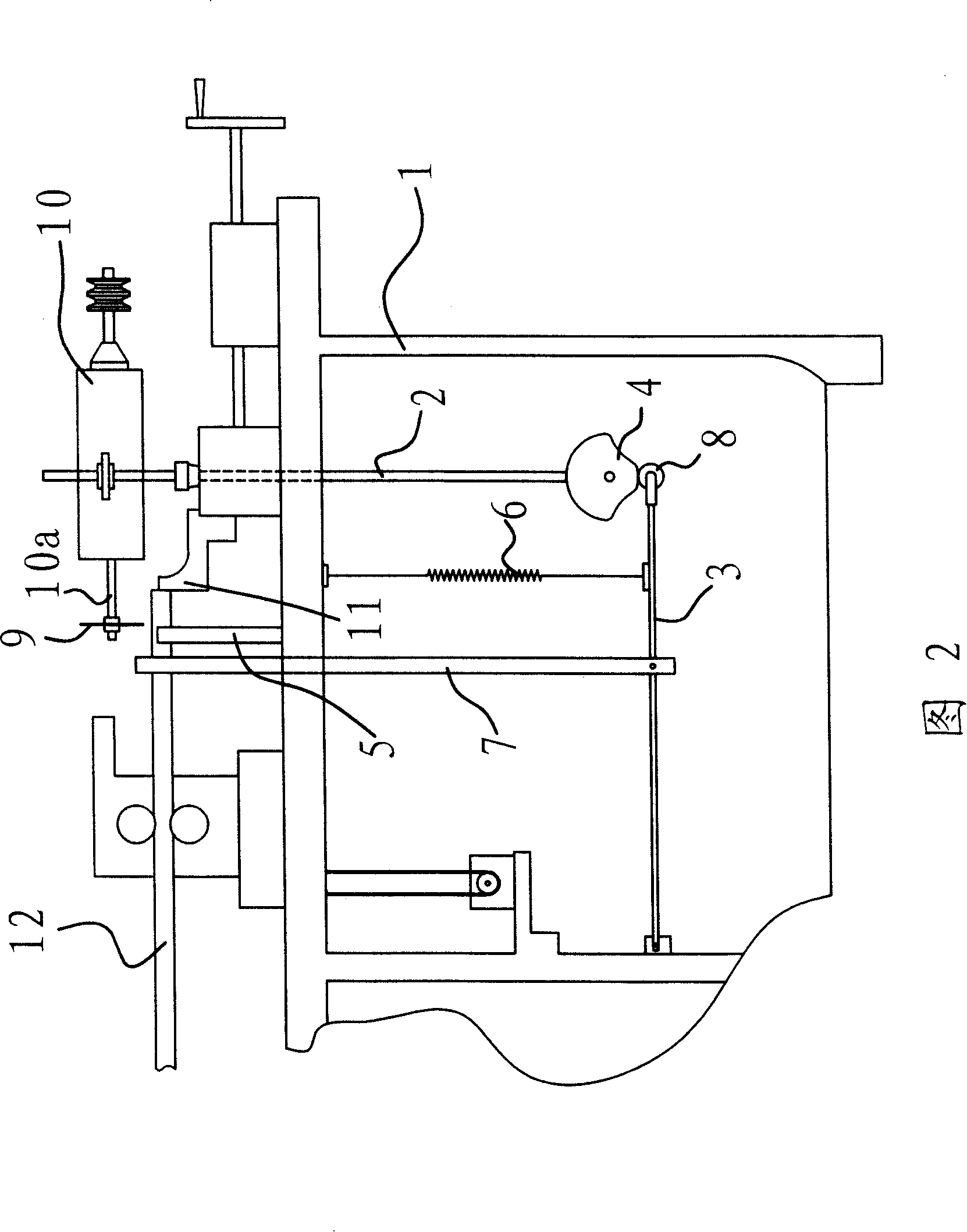
[0021] As shown in Figures 1 and 2, the cutting mechanism of the automatic bar cutting machine is installed in the body 1 of the cutting machine. It includes parts such as connecting rod 2, cross bar 3, cam 4, support block 5, spring 6, pressing bar 7 and pulley 8.

[0022] As shown in FIG. 2 , the cam 4 is fixedly connected in the fuselage 1 , and the cam 4 is driven to rotate by a motor. The connecting rod 2 is vertically arranged, and the upper end of the connecting rod 2 protrudes from the fuselage 1 and is fixedly connected with the motor 10 . The lower end of the connecting rod 2 is in the fuselage 1, and its end is pressed against the edge of the cam 4.

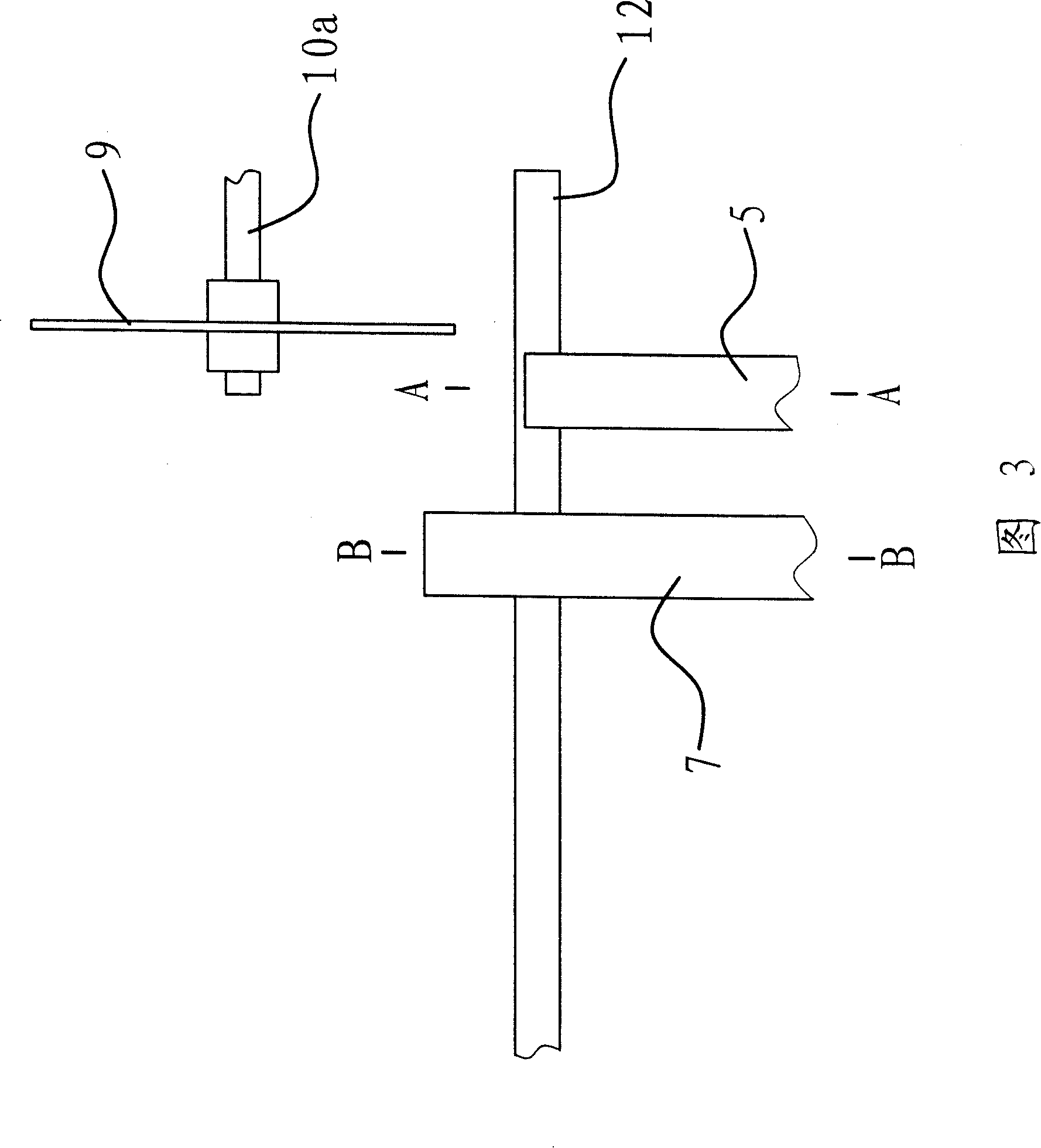
[0023] The blade 9 is at the discharge of the cutting machine. The blade 9 is fixed on the rotating shaft 10 a of the motor 10 . The rotation of blade 9 is driven by motor 10 . Simultaneously, by the rotation of cam 4, blade 9 has been moved up and down.

[0024] There is a cross bar 3 in the fuselage 1, and the c...


PUM


Abstract

A cutting mechanism for automatic rod cutter is composed of an electric motor, cutting blades fixed to shaft of motor, a cam, a vertically moving connection rod with a top end linked to motor and a lower end in touch with said cam, a supporting block at discharge exit, a transverse bar, and a press rod with lower end connected to said transverse bar. Its advantage is correct cutting length.

Description

technical field [0001] The invention belongs to the technical field of machinery, and relates to an automatic bar cutting machine, in particular to a cutting mechanism of the automatic bar cutting machine. Background technique [0002] In the process of parts processing, it is often necessary to cut a bar into several sections before processing. A cutting machine is a common processing equipment used to cut bar stock. [0003] At present, the most advanced is the automatic cutting machine. As the Chinese Patent Publication No. CN2645832 provides "the automatic bar cutting machine with sliding positioning device", it is made up of a bed, a transmission system, a cutting system and a feeding system, and the transmission system adjusts the required cutting length; the feeding system will The bar is transported to the cutting place; the bar is blocked by the stopper so that it cannot move forward; at this time, the blade on the cutting system cuts the bar through the cylinder....

Claims


Application Information

Patent Timeline
Patent Type & Authority Patents(China)
IPC IPC(8): B23D17/04B23D33/02
Inventor 郭增厚应如华
Owner 玉环县三合机床厂(普通合伙)
Why Eureka
Try Eureka