Long-life high-efficiency die-casting punching head

A technology of die-casting punches and bosses, which is applied in the field of metal die-casting, can solve problems such as high production costs, increased total costs, and accelerated wear of pressure chambers, and achieve further improvement and stability promotion of quality, improvement of efficiency and comprehensive economic benefits, The effect of improving punch life

Inactive Publication Date: 2008-07-02
SUZHOU SANJI FOUNDRY EQUIP
View PDF6 Cites 0 Cited by
  • Summary
  • Abstract
  • Description
  • Claims
  • Application Information

AI Technical Summary

Problems solved by technology

Since the die-casting punch is subjected to high speed and high pressure at high temperature when it works in the pressure chamber (barrel), the main failure mode of the die-casting punch is: the punch and the pressure chamber ( The gap between the barrel) is too large, causing the molten metal to escape from the punch and the pressure chamber (barrel) during the die-casting process (commonly known as: running material), so that the molten metal cannot build up high pressure and fail
On the one hand, the punch moves at high speed in the pressure chamber, which determines that there must be a certain gap between the punch and the pressure chamber; on the other hand, the injection force of the die-casting machine directly acts on the metal liquid through the punch, resulting in The high pressure must be sealed by a reasonable gap between the punch and the pressure chamber. If the gap is too large, it will fail due to material running out. Therefore, this is a serious contradiction.
And the application of above-mentioned new material, new technology, although can improve the wear resistance of punch itself, make the life-span of punch and production efficiency improve to a certain extent, yet, caused the manufacturing cost of punch to improve greatly thus, What is more serious is that the life of the pressure chamber is reduced due to accelerated wear
Because the production cost of the pressure chamber (barrel) is very high, so, economically speaking, such efforts are often not worth the candle, and the total cost is even higher.
[0003] In addition, in the prior art, no new breakthrough has been seen in the structure of the punch itself. The front end face of the punch is always a circular plane perpendicular to the axis, and the front peripheral surface is always a cylindrical working surface. It will fail when it wears to the upper limit of the reasonable gap with the pressure chamber

Method used


Image

  • Long-life high-efficiency die-casting punching head
  • Long-life high-efficiency die-casting punching head
  • Long-life high-efficiency die-casting punching head

Examples


Embodiment Construction

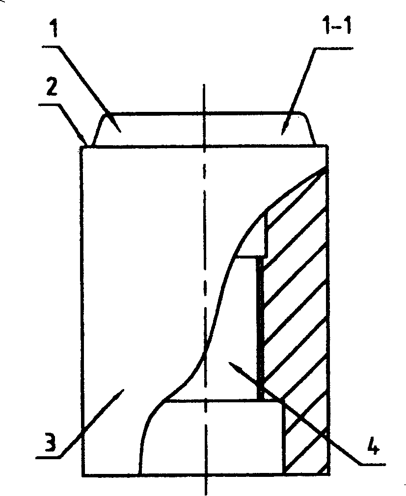
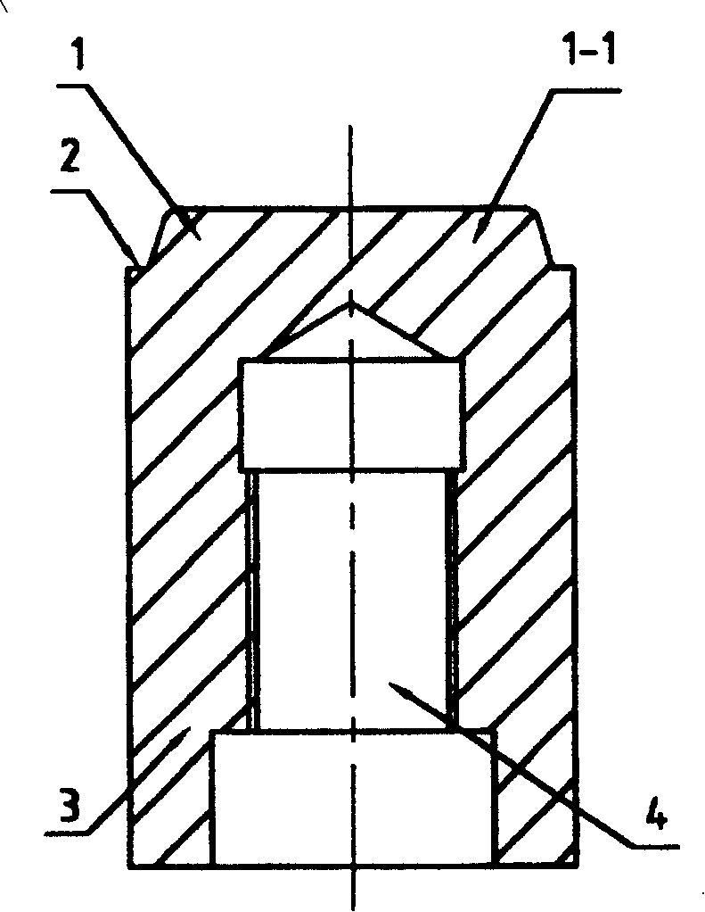
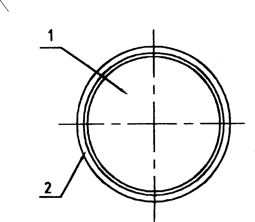
[0013] like figure 1 , 2 , 3 shows the first embodiment of the present invention, as can be seen in the figure, a die-casting punch, the rear end of the punch 3 has a connecting screw hole 4, the improvement is that the front end of the punch 3 has a front end boss 1 , the front end boss 1 is a rotary body 1-1 whose axial section gradually decreases forward, and the axis line of the rotary body 1-1 coincides with the axis line of the punch 3. Certainly, the axis line of the rotary body 1-1 and the axis line of the punch 3 can also be parallel, but the coincidence is easy to process and the effect is better. At the same time, the front end of the punch 3 also has an annular end face 2 , and the rear end of the front end boss 1 , that is, the outer periphery of the rotating body 1 - 1 is connected to the annular end face 2 . The annular end surface 2 is an annular plane perpendicular to the axis of the punch. The rotary body 1-1 is in the shape of a truncated cone, and the ax...


PUM


Abstract

The invention discloses a die cast punch with continuous taps at the back end. The characteristics are: the front end of the punch has a front convex platform that is a gyrorotor or intercept polygon cone with axial section lessening and the axial lead of the gyrorotor parallels or superposes the axial lead of the punch. The front end of the punch also has a ring end face connecting the back end of the convex platform. The platform and the wall of the pressure chamber form a round band area to quickly solidify the alloy melt flowing into the area in order to prevent other high-pressure melt flowing out between the chamber and the punch and the round band area and the feed cake is integrate.

Description

technical field [0001] The invention belongs to the field of metal die-casting and relates to a die-casting punch suitable for a die-casting machine. Background technique [0002] For a long time, die-casting punches used in die-casting machines at home and abroad have been improving the wear resistance of the punch itself by applying new materials, new heat treatment or surface treatment processes, thereby increasing the life of the punch, thereby reducing replacement time and improving production efficiency . For example, CN1114690A uses beryllium-nickel-copper alloy material to replace the commonly used cast iron material for the die-casting punch, that is, to increase its wear resistance by using a new material to improve life and production efficiency. CN2128251Y is to carry out laser scanning hardening treatment at local intervals along the circumferential direction of the die-casting punch made of cast iron material, that is, to increase its wear resistance by adopti...

Claims


Application Information

Patent Timeline
Patent Type & Authority Patents(China)
IPC IPC(8): B22D18/02
Inventor 张山根
Owner SUZHOU SANJI FOUNDRY EQUIP
Why Eureka
Try Eureka