Apparatus and method for base plate conglutination

A technology for bonding devices and substrates, which is applied in the directions of optics, instruments, electrical components, etc., and can solve the problems that the upper substrate 1a and the sealant 5 are not in good contact

Inactive Publication Date: 2008-09-03
SHIBAURA MECHATRONICS CORP
View PDF9 Cites 0 Cited by
  • Summary
  • Abstract
  • Description
  • Claims
  • Application Information

AI Technical Summary

Problems solved by technology

[0018] However, because of the offset contact of the pressing surface of the relatively hard plate member 12a, only the plate member 12a is pushed, as shown in the enlarged important part of the schematic diagram of FIG. expect to improve it

Method used


Image

  • Apparatus and method for base plate conglutination
  • Apparatus and method for base plate conglutination
  • Apparatus and method for base plate conglutination

Examples


Embodiment Construction

[0036] Refer to the following Figure 4 to Figure 9 An embodiment of the substrate bonding method and the substrate bonding apparatus of the present invention will be described in detail. Also, in Figure 4 to Figure 11 in, for with figure 1 The same structures as the conventional structure shown in FIG. 3 are assigned the same symbols and detailed description thereof will be omitted.

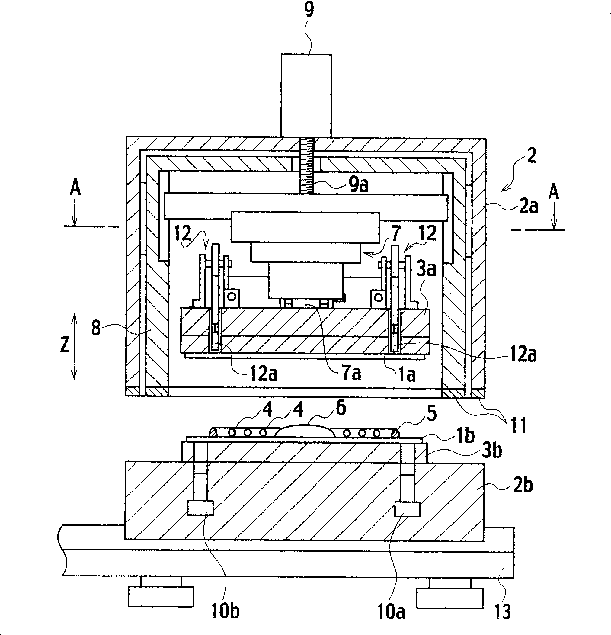
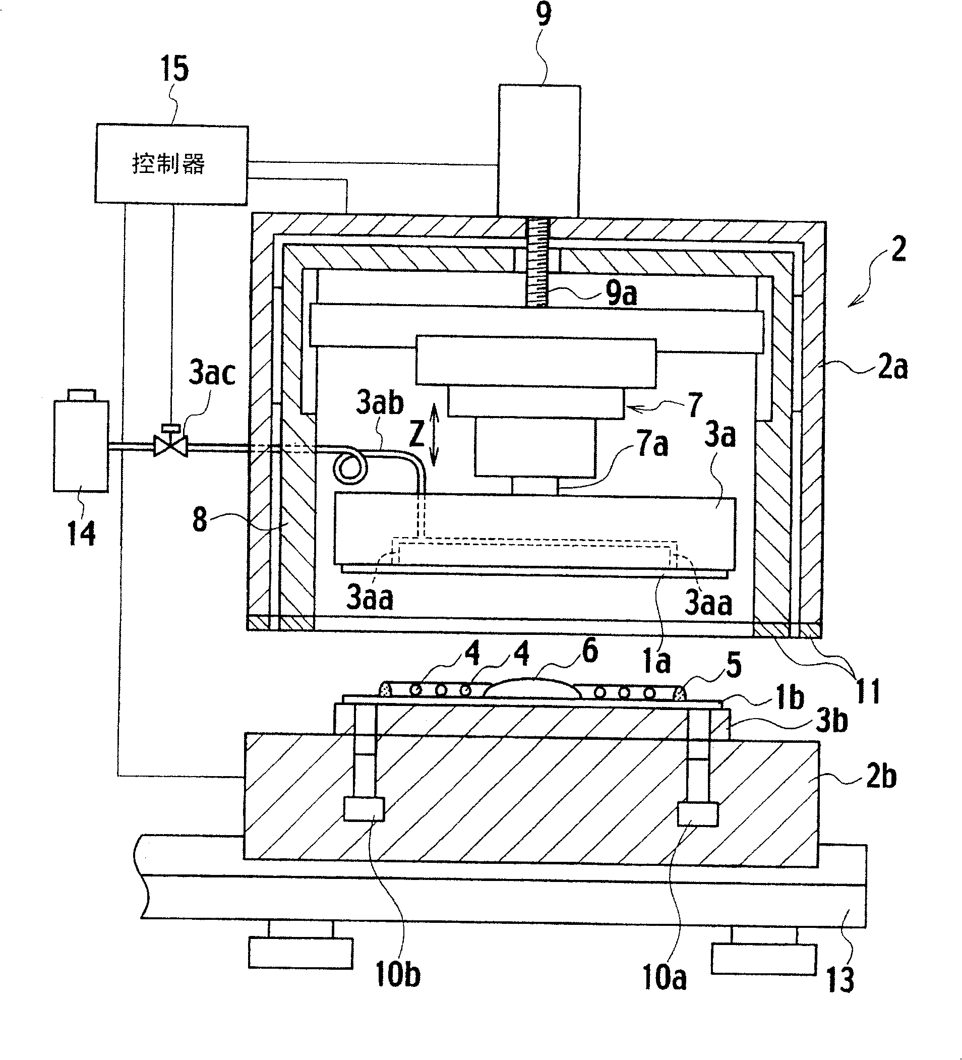
[0037] Figure 4 It is a configuration diagram showing the first embodiment of the substrate bonding apparatus of the present invention.

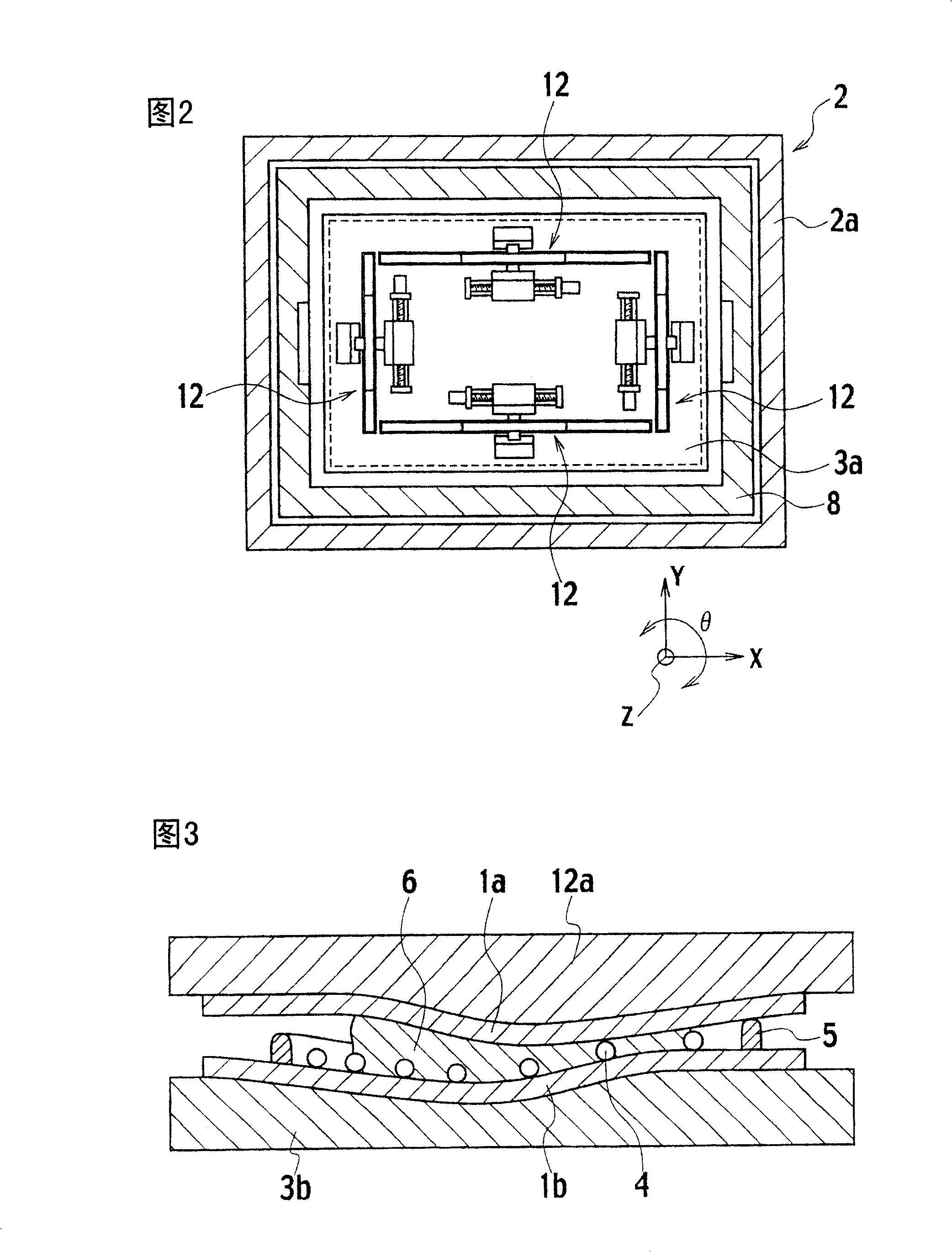
[0038] exist Figure 4 Among them, the substrates 1a, 1b made of thin glass constituting a pair of upper and lower rectangular shapes are in the chamber 2 composed of the upper and lower chambers 2a, 2b, and the upper substrate 1a is held on the lower surface of the upper chuck 3a by suction, etc. 1b is placed and held on top of the lower suction cup 3b.

[0039] The display surface of the lower substrate 1b is provided with a spacer 4 in advance, an a...


PUM


Abstract

To provide an apparatus for laminating substrate and a method for sticking substrate for satisfactorily laminating upper and lower substrates across a sealant by reducing intrusion of air bubbles to a liquid crystal display surface. In laminating the upper substrate 1a to lower substrate 1b across the sealant 5, discharge holes 3aa of gas are formed on the upper stage 3a and discharged gas from the discharge holes 3aa is directed to the inner side of a line to which the sealant 5 is applied. In the thin upper and lower substrates 1a, 1b laminated to each other in the vacuum environment, even when connection between the sealant 5 and the upper substrate 1a is not properly performed by the pushing operation 3a of the stage 3a, the sealant 5 is pressurized and is properly crushed by substrate deformation by the discharged gas along the sealant 5. Further, since the discharged gas pushes a substrate surface located on a position more inside than the position of the sealant 5, it is avoided that the discharged gas sneaks in along the substrate edge and flows into a cell and that the air bubble remains on the display surface, and a satisfactory liquid crystal display panel can be manufactured.

Description

technical field [0001] The present invention relates to the improvement of suitable substrate bonding apparatus and substrate bonding method used in the manufacture of liquid crystal display panels. Background technique [0002] Generally, liquid crystal display panels used in displays such as personal computers, TV receivers, or various monitors are a pair of thin glass substrates that are opposed to each other, and are sealed in a frame shape by applying a frame-like seal to surround the display surface. Adhesive bonding to manufacture. In addition, in order to make the interval between bonded substrates (element interval) constant, a plurality of spacers are provided in advance on the display surface of the substrate. [0003] A liquid crystal display panel is formed by encapsulating liquid crystals in the display surfaces of two bonded substrates. There are injection methods and dripping methods for liquid crystal encapsulation on the display surfaces. [0004] figure...

Claims


Application Information

Patent Timeline
Patent Type & Authority Patents(China)
IPC IPC(8): G02F1/1333
CPCG02F1/133308G02F1/1339G02F2202/28H10K50/841
Inventor 高桥崇史石山英一牧野勉
Owner SHIBAURA MECHATRONICS CORP
Why Eureka
Try Eureka