Energy-saving fuel battery stack with air supplying apparatus

A fuel cell stack and air supply technology, applied in fuel cells, fuel cell additives, fuel cell grouping, etc., can solve the problems of reducing power density, increasing the complexity of fuel cell systems, and inability to distribute air baffles evenly, etc. To achieve the effect of uniform air flow

Active Publication Date: 2008-09-03
SHANGHAI MUNICIPAL ELECTRIC POWER CO +1
View PDF6 Cites 0 Cited by
  • Summary
  • Abstract
  • Description
  • Claims
  • Application Information

AI Technical Summary

Problems solved by technology

Such distribution of multiple fans will inevitably increase the complexity of the fuel cell system and reduce the power density of the entire system
[0014] ②The upper and lower fans form an air flow during operation, which cannot be evenly distributed on all the air deflectors in the entire fuel cell stack
[0015] ③ It is easy to bring dust, water, impurities and other harmful substances into the fuel cell stack and stay in each air deflector

Method used


Image

  • Energy-saving fuel battery stack with air supplying apparatus
  • Energy-saving fuel battery stack with air supplying apparatus
  • Energy-saving fuel battery stack with air supplying apparatus

Examples


Embodiment

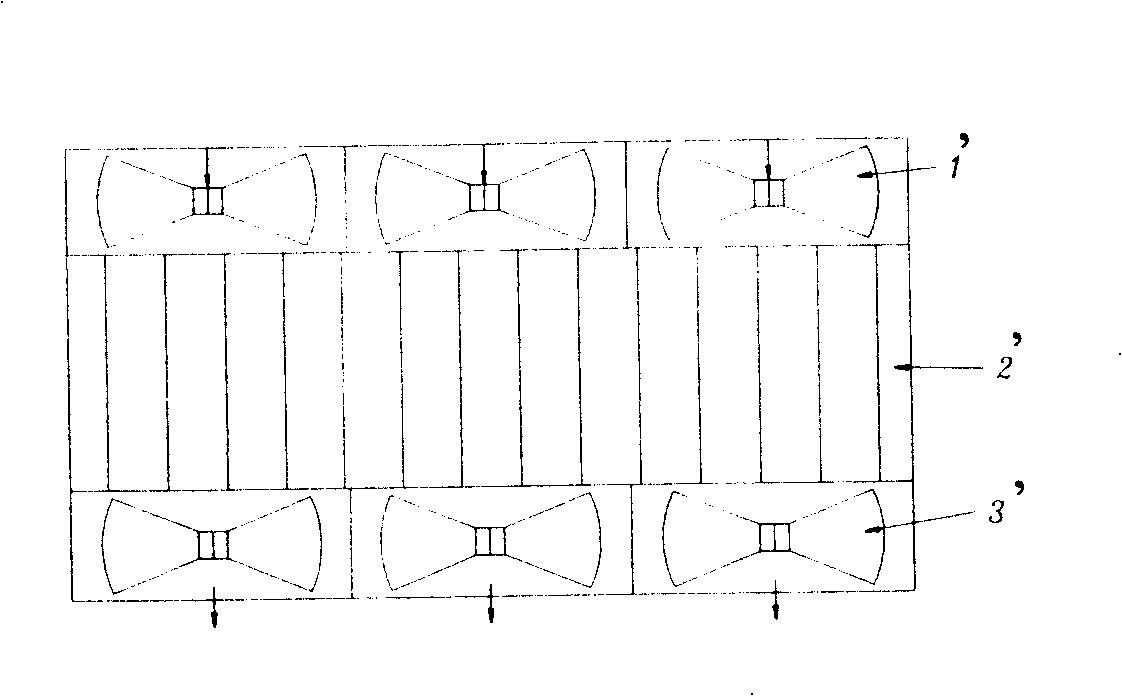
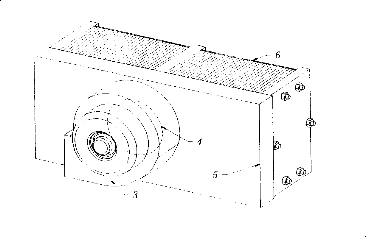
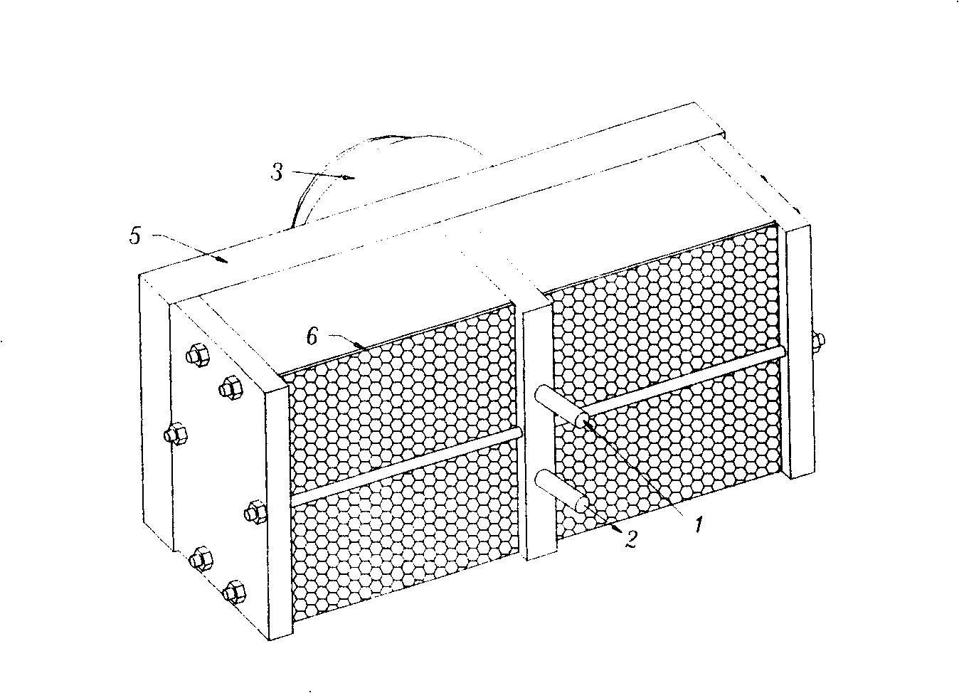
[0030] Such as figure 2 , image 3 As shown, an energy-saving fuel cell stack with an air supply device has a length, width, and height of 275mm×83mm×132mm. The fuel cell stack includes membrane electrodes, guide plates, current collector plates, front and rear end plates, Fasten the tie rods, and also include an air supply device, the air supply device includes a fan 3, and an air collecting cover 5, and the air collecting cover 5 covers the end surface formed by all the air guide grooves on one side of the fuel cell stack, There is a hole 4 in the middle of the air collecting cover, and the opening 4 is connected to the suction port of the fan 3; when the fan is working, a negative pressure is generated due to the action of the air collecting cover 5, so that all the air on the other side of the battery stack Air is sucked in at the end faces where the guide grooves are assembled. A layer of air filter 6 is laid on the end face of all the air guide slots on the other side...


PUM


Abstract

This invention relates to energy saving fuel battery pile with air supply device, which comprises film electrode, flow guide electrode board, flow collection parent board, front and back end board, tight push board and air supply device, wherein, the air supply device comprises wind blower, air collection flow cover; the cover is on air flow cover to fuel battery side end surface; the air collection flow cover middle is opened with holes connected to the wind absorptive mouth; when wind machine works, due to air collection to generate load voltage with other side absorbed end of all air guide tank.

Description

technical field [0001] The invention relates to a fuel cell, in particular to an energy-saving fuel cell stack with an air supply device. Background technique [0002] An electrochemical fuel cell is a device that converts hydrogen and oxidants into electrical energy and reaction products. The internal core component of the device is the membrane electrode (Membrane Electrode Assembly, referred to as MEA). The membrane electrode (MEA) is composed of a proton exchange membrane and two porous conductive materials, such as carbon paper, sandwiched between the two sides of the membrane. On the two boundary surfaces of the membrane and the carbon paper, there are even and finely dispersed catalysts for initiating electrochemical reactions, such as metal platinum catalysts. Conductive objects can be used on both sides of the membrane electrode to draw the electrons generated during the electrochemical reaction through an external circuit to form a current loop. [0003] At the a...

Claims


Application Information

Patent Timeline
Patent Type & Authority Patents(China)
IPC IPC(8): H01M8/04H01M8/10H01M8/24H01M8/00H01M8/0258H01M8/04746
CPCY02E60/521Y02E60/50
Inventor 葛栩栩王立明李创李丽夏建伟章波胡里清
Owner SHANGHAI MUNICIPAL ELECTRIC POWER CO
Why Eureka
Try Eureka