Pulsating fluid-bed combustion apparatus

A combustion device and fluidized bed technology, which is applied in the direction of fluidized bed combustion equipment, fuel for combustion in a molten state, and combustion methods, etc., can solve the problems of high noise in pulsating combustion hot water boilers, and achieve accelerated chemical reaction speed and heat transfer The effect of high efficiency and high combustion intensity

Inactive Publication Date: 2008-09-17
ZHEJIANG UNIV
View PDF2 Cites 2 Cited by
  • Summary
  • Abstract
  • Description
  • Claims
  • Application Information

AI Technical Summary

Problems solved by technology

In the 1950s and 1960s, people began to apply pulsating combustion technology to heating and heating. Lucax-Rotax pulsating combustion hot water boilers were launched in Canada, but due to the low fuel price at that time and the excessive noise of pulsating combustion hot water boilers, etc. , preventing it from being promoted

Method used


Image

  • Pulsating fluid-bed combustion apparatus
  • Pulsating fluid-bed combustion apparatus
  • Pulsating fluid-bed combustion apparatus

Examples


Embodiment Construction

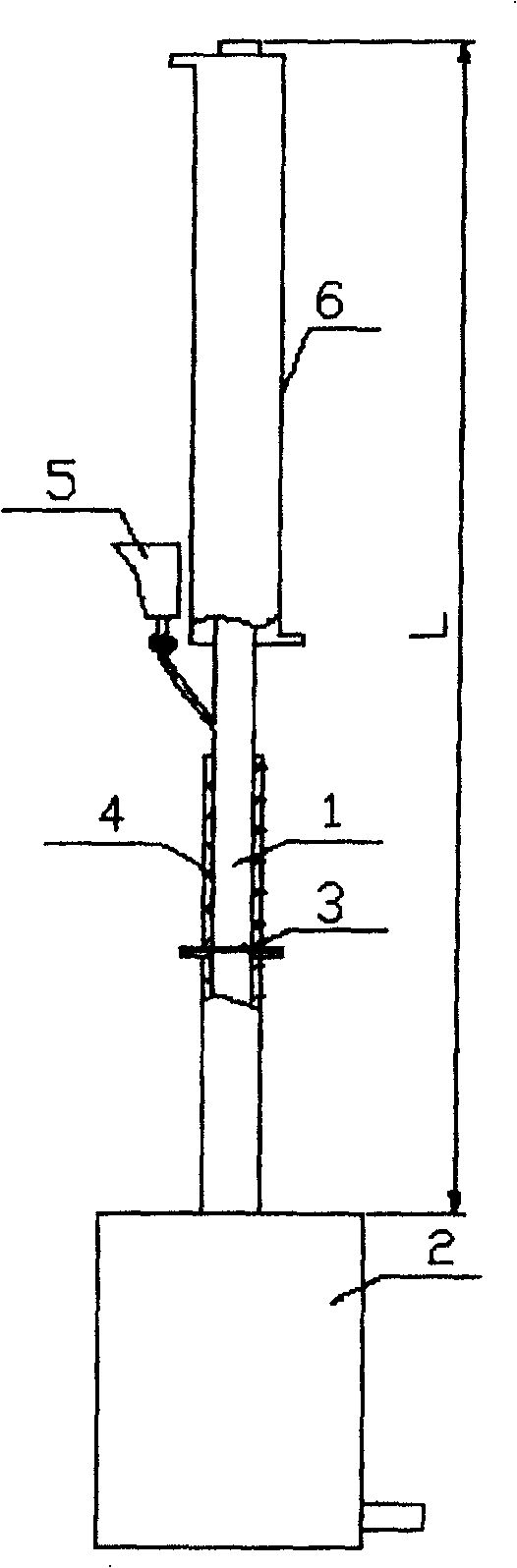
[0021] As shown in the attached figure, the pulsating fluidized bed combustion device has an acoustic decoupling chamber 2, and a Rick tube type pulsating fluidized bed combustion body 1 is connected to the acoustic decoupling chamber 2, and a Rick tube type pulsating fluidized bed combustion The L / 12-3L / 4 of the chamber main body 1 is provided with an air distribution plate 3, where L is the length of the main body tube of the combustion chamber, and a heating plate is provided outside the main wall of the Rick tube type pulsating fluidized bed combustion chamber above and below the air distribution plate. The device 4 is provided with a heat exchange surface 6 on the outer wall of the main body 1 of the Rick tube type pulsating fluidized bed combustor, and the Rick tube type pulsating fluidized bed combustor between the heat exchange surface 6 and the heating device 4 A feeding device 5 is provided on the side wall of the main body.

[0022] The air distribution plate 3 is s...


PUM


Abstract

The invention discloses a pulsating fluidized bed combustion apparatus. It includes: acoustic decoupling chamber. Reike tube type pulsating fluidized bed combustion chamber main body is connected with acoustic decoupling chamber; airing plate is set at L / 12-3L / 4 position of the pulsating fluidized bed combustion chamber. L is the length of the combustion chamber main tube. Heating device is installed at the outer side of main body wall of pulsating fluidized bed combustion chamber. The heat exchanging surface is set at the inner or outer wall of the upper of the pulsating fluidized bed combustion chamber main body. The feeding device is installed at the side wall of the pulsating fluidized bed combustion chamber main body between heat exchanging surface and heating apparatus. The invention combines the pulsating combustion technique with fluidized bed combustion technique. It's a novel combustion conception.

Description

technical field [0001] The invention relates to a combustion device, in particular to a pulsating fluidized bed combustion device. Background technique [0002] Pulsating combustion describes the combustion process that occurs under the condition of airflow parameters, that is, state parameters in the combustion zone, such as temperature, pressure, speed, etc., which fluctuate periodically with time. The development of pulse combustion technology has gone through a long iterative process. In 1900, Gobble applied for the first German patent for a pulsating combustion device, but the structure of its air circulation control mechanism was too complicated to be put into practical application; in 1906, Esnault-Pelterie applied for a mechanical diaphragm self-excited oscillating pulsating burner French patent, its essence is a device that uses a pulsating burner to drive a gas turbine; in 1908, Lorin designed a pulsating combustion jet engine; in 1909, Marconnet developed an aero...

Claims


Application Information

Patent Timeline
Patent Type & Authority Patents(China)
IPC IPC(8): F23C10/00F23C101/00
Inventor 程乐鸣骆仲泱王勤辉施正伦周劲松余春江岑可法
Owner ZHEJIANG UNIV
Why Eureka
Try Eureka