Alcohol-base fuel burner with radiant panel fuel nozzle

A technology for fuel nozzles and alcohol-based fuels, applied in burners, combustion methods, combustion types, etc., can solve the problems of unstable combustion, high fuel quality requirements, and poor liquid vaporization, and achieve improved combustion performance and safety performance. , Strengthen the effect of radiation heat transfer and avoid the effect of tempering

Inactive Publication Date: 2009-12-09
湖南中能力华新能源技术有限公司 +1
View PDF0 Cites 7 Cited by
  • Summary
  • Abstract
  • Description
  • Claims
  • Application Information

AI Technical Summary

Problems solved by technology

The disadvantages are: low combustion temperature, incomplete combustion of alcohol-based fuel, low thermal efficiency, and a large amount of harmful gases, polluting the environment and wasting energy
The existing problems are: (1) due to the low-pressure liquid supply, the firepower gradually increases, if the vaporization is insufficient, the combustion is unstable, and there is panting phenomenon; (2) the liquid flow control is difficult; (3) the thermal efficiency is low, and the fuel quality is high. Otherwise the liquid will not vaporize well
The temperature of the fuel tank of this kind of burner is high, the pressure is high, and it is always fluctuating. Under certain circumstances, the pressure in the fuel tank may rise sharply, which may cause the fuel tank to explode, and there is a great safety hazard
The above three burners all have different defects, and their thermal efficiency is only 26-32%, CO ≥ 200ppm, some burners CO emissions are even higher than 1200ppm, NOx ≥ 40ppm, can not really achieve the purpose of energy saving, environmental protection and high efficiency

Method used


Image

  • Alcohol-base fuel burner with radiant panel fuel nozzle
  • Alcohol-base fuel burner with radiant panel fuel nozzle
  • Alcohol-base fuel burner with radiant panel fuel nozzle

Examples


Embodiment Construction

[0027] The present invention will be further described below in conjunction with the accompanying drawings.

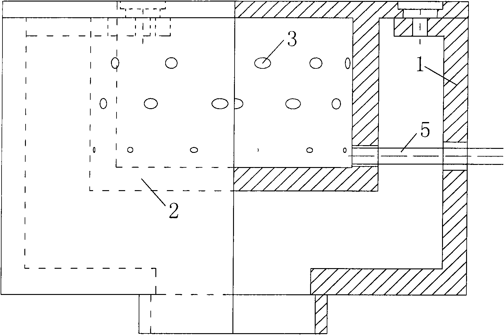
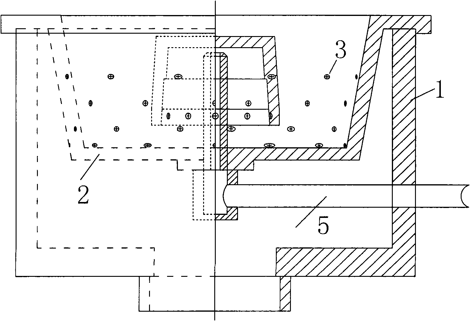
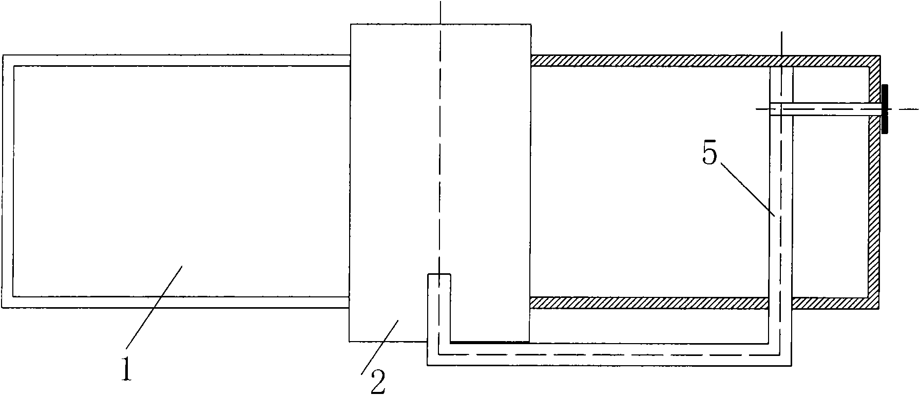
[0028] See attached Figure 4 , 5 , 6, 7, 8, the embodiment of the present invention, the alcohol-based fuel burner with radiant plate fuel nozzle, comprises air cavity 1, combustion mixing combustion chamber 2, atomizing injection pipe 4, and described air cavity 1 is opened at one end, and another One end is provided with a tuyere 8; the combustion and mixed combustion chamber 2 is a cylinder with a bottom plate at one end and an opening at the other end, and an air hole 3 is arranged on the cylinder wall, and the combustion and mixed combustion chamber 2 is set in the wind In the cavity 1, the open ends of the two are in the same direction and are fixedly connected and positioned through the open ends; the cylindrical wall of the combustion and combustion chamber 2 is evenly distributed with three circles of air holes 3, and between the two adjacent circles of air ...


PUM


Abstract

An alcohol-base fuel burner with radiant panel fuel nozzle comprises an air chamber, a mixed combustion chamber, an atomization injection pipe, wherein one end of the air chamber is opened, and the other end thereof is provided with an air inlet; the mixed combustion chamber is sleeved in the air chamber and is provided with air holes along the wall of the mixed combustion chamber; the center of the atomization injection pipe is a through hole, one end is provided with a radiant panel, the other end is installed on the soleplate of the mixed combustion chamber and is communicated with one end of a fuel supply pipe, and at least two fuel injection holes are uniformly distributed on the same cross section of the wall of the atomization injection pipe. The invention has high combustion efficiency, low energy consumption and less pollutant emission; compared with the existing technology, the discharge amount of CO and NOx is relatively reduced by 50% to 70%, and the heat efficiency reaches up to more than 40%. The burner is safe, environment-friendly, stable in combustion, high in combustion strength, easy and safe for combustion, good in fire adjustment, high-temperature and corrosion resistant, high impact resistant, mechanical impact resistant, low in thermal inertia and long in service life; and the burner is suitable for being applied to various special cookers in catering industry.

Description

technical field [0001] The invention relates to an alcohol-based fuel burner, in particular to an alcohol-based fuel burner with a radiant plate fuel nozzle. Background technique [0002] Currently, there are three alcohol-based fuel burners on the market: see attached figure 1 , the first type is the liquid surface direct combustion type. It is to inject a certain amount of alcohol-based fuel directly into the small container of the stove, and the combustion and vaporization are carried out simultaneously on the liquid surface. The disadvantages are: low combustion temperature, incomplete combustion of alcohol-based fuel, low thermal efficiency, and a large amount of harmful gases, polluting the environment and wasting energy. See attached figure 2 , the second type is liquid fuel pressurized. It adopts a downward opening cup, and the inflowing liquid absorbs the heat of the cup, vaporizes and pressurizes, and sprays out from the small hole on the cup. The existing pr...

Claims


Application Information

Patent Timeline
Patent Type & Authority Applications(China)
IPC IPC(8): F23D11/00F23D11/36F23D11/40F23D11/44
Inventor 张全周明杨正辉杨琦
Owner 湖南中能力华新能源技术有限公司
Why Eureka
Try Eureka