Turbulent combustor allowing premixed gas flow to force flue gas to flow back for preheating combustion

A swirling burner and flue gas technology, applied in the direction of gas fuel burners, burners, combustion methods, etc., can solve the problems of incomplete combustion, low combustion temperature, uneven mixing, etc., to reduce the temperature of exhaust gas and reduce the environment Pollution, stability improvement effect

Active Publication Date: 2014-07-02
陈维汉
View PDF10 Cites 8 Cited by
  • Summary
  • Abstract
  • Description
  • Claims
  • Application Information

AI Technical Summary

Problems solved by technology

[0003] In view of the above situation, in order to overcome the defects of the prior art, the present invention provides a swirl burner for forced flue gas backflow and preheating combustion by premixed air flow, which can effectively solve the problem of low mixing rate of gas and air, uneven mixing, low combustion intensity and poor combustion efficiency. Problems such as low temperature, incomplete combustion, large combustion chamber space and unreasonable burner structure

Method used


Image

  • Turbulent combustor allowing premixed gas flow to force flue gas to flow back for preheating combustion
  • Turbulent combustor allowing premixed gas flow to force flue gas to flow back for preheating combustion
  • Turbulent combustor allowing premixed gas flow to force flue gas to flow back for preheating combustion

Examples


Embodiment Construction

[0009] The specific implementation manners of the present invention will be described in detail below in conjunction with the accompanying drawings.

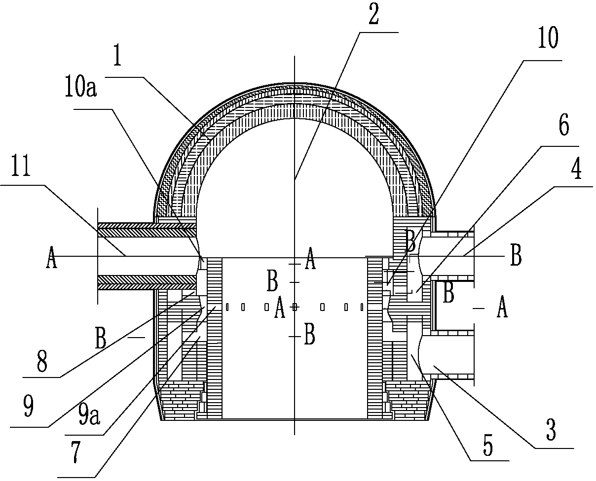
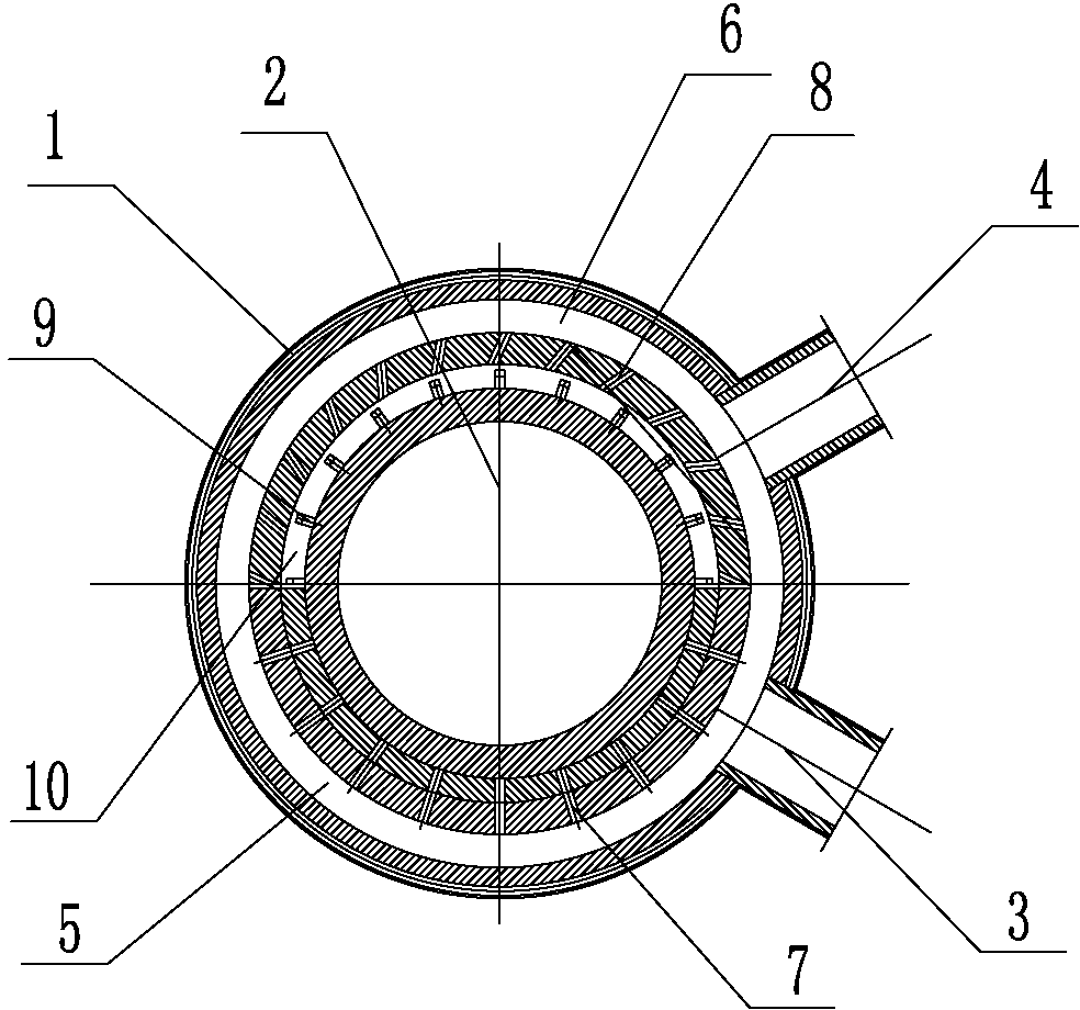
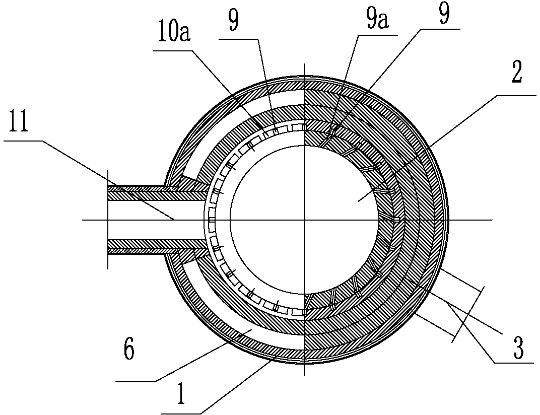
[0010] Such as figure 1 , figure 2 and image 3 As shown, the present invention includes a combustion chamber wall 1, a combustion chamber 2, a hot air outlet pipe 11, an air intake pipe 3, a gas intake pipe 4, an air distribution channel 5, a gas distribution channel 6, an air outlet pipe 7, and a gas outlet nozzle 8 , air injection nozzle 9, flue gas suction port 9a, gas-air premixing passage 10 and premixed gas vertical upward nozzle 10a, the combustion chamber wall 1 is composed of a hemispherical vault at the top and a cylindrical wall at the bottom The internal space of the wall of the combustion chamber is the combustion chamber 2, and the upper and lower walls of the cylinder of the combustion chamber wall 1 are staggered and arranged with a gas inlet pipe 4 and an air inlet pipe 3 perpendicular to the cylinder. The ...


PUM


Abstract

The invention relates to a turbulent combustor allowing premixed gas flow to force flue gas to flow back for preheating combustion. The turbulent combustor effectively solves the problems that the mixing rate of coal gas and air is low, mixing of the coal gas and the air is not uniform, combustion intensity is low, temperature is low, mixing is incomplete, space is large, and the structure is unreasonable. A combustion chamber is formed in a combustion chamber wall. An air inlet pipe and a coal gas inlet pipe on the combustion chamber wall are connected with an air distribution channel and a coal gas distribution channel. The coal gas distribution channel is provided with a coal gas lead-out nozzle which is connected with a coal gas and air premixing channel. The air distribution channel is provided with an air lead-out pipe which is connected with an air ejecting nozzle. The air ejecting nozzle is connected with the coal gas and air premixing channel. The top of the coal gas and air premixing channel is provided with a vertically upward premixed gas nozzle. The combustion chamber wall is provided with a hot air outlet pipe. According to the turbulent combustor, it is guaranteed that a hot-blast stove efficiently operates in high heat intensity at high air supply temperature under the premise of being safe and stable, so that the good effects of saving fuel, reducing investments, lowering exhaust gas temperature and harmful gas emissions and reducing environmental pollution are achieved.

Description

technical field [0001] The invention relates to a burner for a hot blast stove of a blast furnace, in particular to a swirl burner for preheating and burning of a premixed air flow for forced flue gas backflow to provide high-temperature blast for the blast furnace. Background technique [0002] At present, considering energy saving and consumption reduction, blast furnace hot blast stoves are required to obtain high performance and high blast temperature under the combustion of low calorific value blast furnace gas, and finally achieve the goals of high efficiency, energy saving, environmental protection, and increased production. For this reason, an optimized combustion process must be combined with an enhanced heat transfer process in the hot blast stove. This involves the structure of the combustion device, the structure and arrangement of the heat storage body, and the organization of the air flow field, especially the influence of the structure and performance of the b...

Claims


Application Information

Patent Timeline
Patent Type & Authority Applications(China)
IPC IPC(8): F23D14/02F23D14/62F23D14/66C21B9/14
CPCY02E20/34
Inventor 陈维汉
Owner 陈维汉
Why Eureka
Try Eureka