Glass liner structure of vacuum electric heating vessel

A vacuum and container technology, which is applied in the field of the bladder structure of a vacuum electric heating container, can solve the problems of poor processing technology of the bladder, affecting the quality of the kettle body, and inconvenient welding of the inner bladder, so as to ensure the vacuum degree, ensure the welding quality, The effect of improving the manufacturability

Inactive Publication Date: 2008-12-10
白明军 +1
View PDF9 Cites 8 Cited by
  • Summary
  • Abstract
  • Description
  • Claims
  • Application Information

AI Technical Summary

Problems solved by technology

[0002] The separate three-layer vacuum electric heat preservation vessel is an invention patent applied by the applicant on January 6, 2004. The patent number is 200410012628. It can keep warm, but because the heating layer is located at the bottom of the inner tank, it is inconvenient to weld with the inner tank, and the processing technology of the inner tank is not good, which often affects the quality of the pot body

Method used


Image

  • Glass liner structure of vacuum electric heating vessel
  • Glass liner structure of vacuum electric heating vessel
  • Glass liner structure of vacuum electric heating vessel

Examples


Embodiment 1

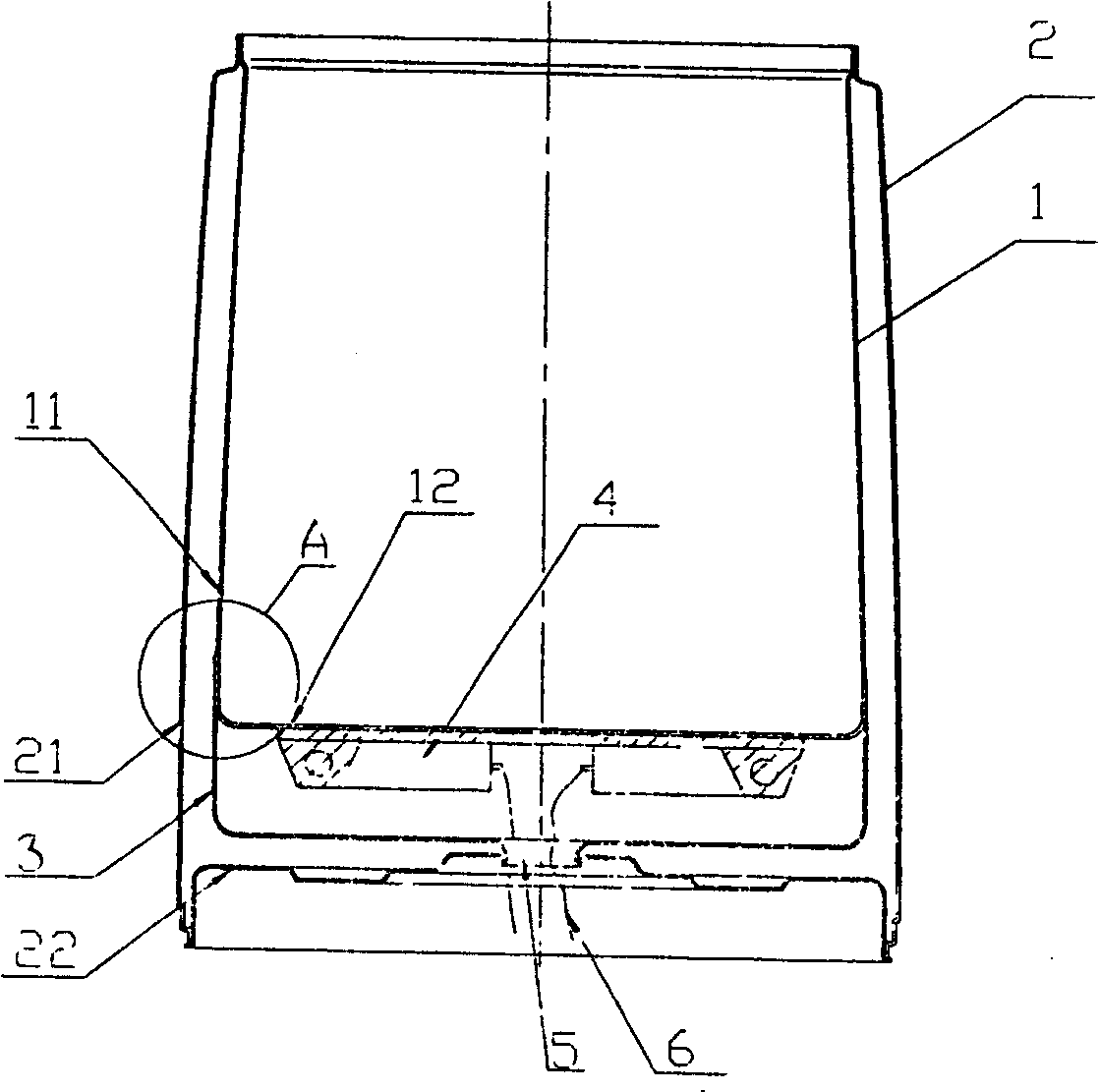
[0016] Embodiment 1: This embodiment includes an inner tank 1 , an outer tank 2 , a vacuum connection layer 3 and an electric heating device 4 . The inner tank is composed of an upper inner tank 11 and a lower inner tank 12; the electric heating device 4 is composed of an aluminum alloy heat dissipation material and an electric heating wire arranged in the aluminum alloy heat dissipation material, and is located between the inner tank 1 and the vacuum connection layer 3 , the aluminum alloy heat dissipation material is placed on the back of the bottom inner tank 12, and the bottom inner tank 12 is welded with the bottom. Boil-dry prevention device and temperature sensor can be provided at the back of bottom liner 12 . The outer bladder is composed of an upper outer bladder 21 and a bottom outer bladder 22, and the upper outer bladder 21 and the lower outer bladder 22 are sealed and welded together at the corners. The bottom back of the inner container in the space formed betw...

Embodiment 2

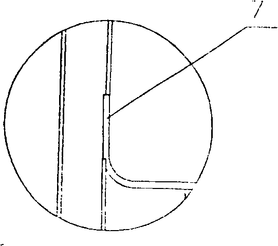
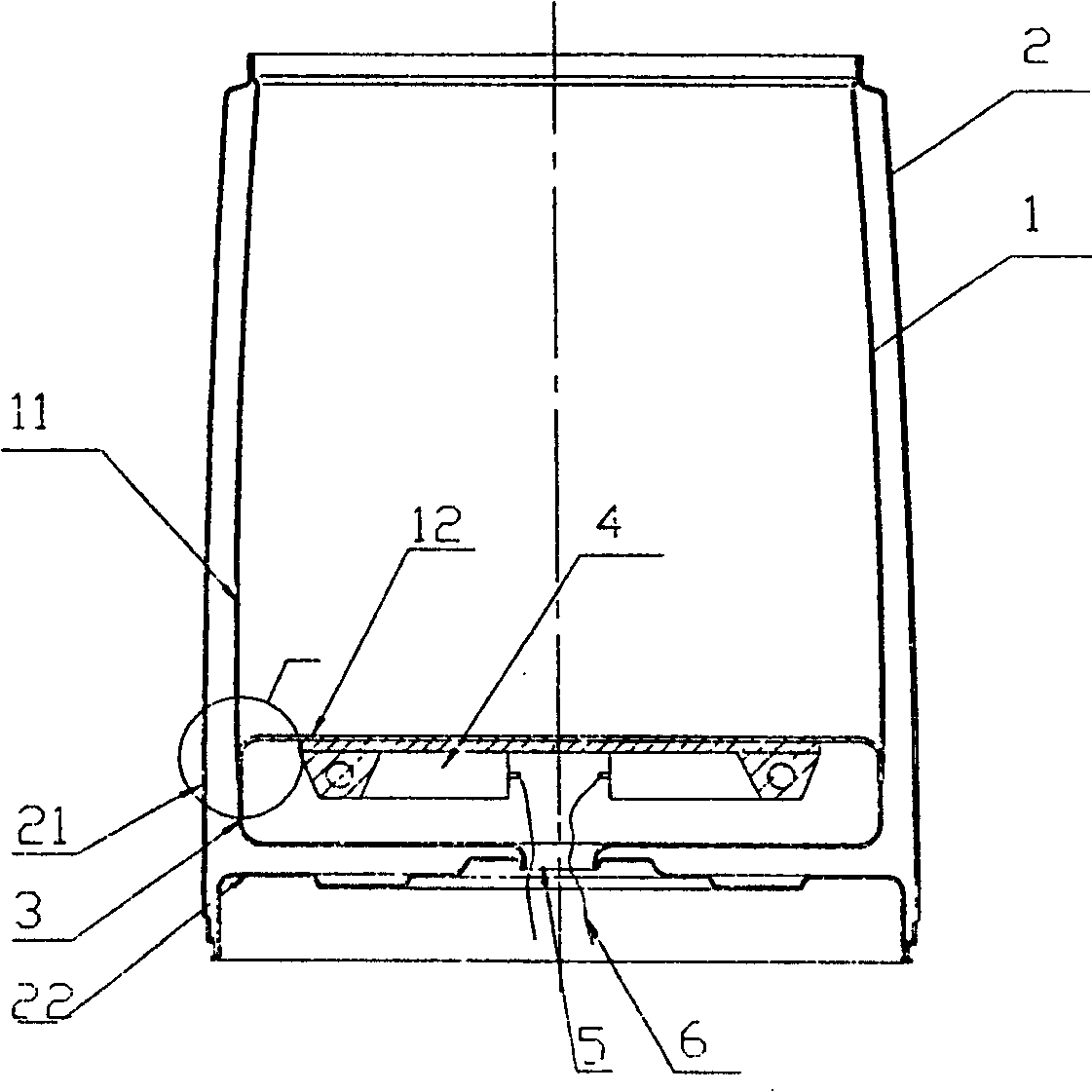
[0017] Embodiment 2: This embodiment includes an inner container 1 , an outer container 2 , a vacuum connection layer 3 and an electric heating device 4 . Its structure is basically the same as that of Embodiment 1, the difference is that the bottom liner 12 is provided with a downward folded edge 8 around the periphery, and the outer end of the vacuum connection layer 3 is sealed with the outer end of the bottom liner 12 lower folded edge 8 Welding, a sunken circular step is processed along the circumferential direction on the outer surface of the root of the lower flange of the bottom inner tank 12, and the lower end of the upper inner tank 11 is set on the sunken circular step at the root of the lower flange 8 of the bottom inner tank to seal against it Welding can fully guarantee the welding quality.

[0018] After the above structure is adopted in the present invention, the manufacturability of the tank structure of the vacuum electric heating container can be greatly imp...


PUM


Abstract

A liner structure of vacuum electric heating vessel includes an internal container (1), an external casing (2), a vacuum connecting layer (3) and an electric heating device (4). The internal container (1) and the external casing (2) are seal welded at the openings of the containers. The said vacuum connecting layer (3) is set between the bottom of the internal container (1) and the bottom of the external casing (2) and its edge is seal welded to the bottom of the internal container (1). The said electric heating device (4) is located between the internal container (1) and the vacuum connecting layer (3) and welded covering the bottom of the internal container (1). Two through holes (5) for passing of power cords or signal lines are on the bottoms of the vacuum connecting layer (3) and the external casing (2). The two through holes (5) are seal welded at corresponding edges.

Description

technical field [0001] The invention relates to a vacuum electric heating container, in particular to a vacuum electric heating container gall body structure. Background technique [0002] The separate three-layer vacuum electric heat preservation vessel is an invention patent applied by the applicant on January 6, 2004. The patent number is 200410012628. It can keep warm, but because the heating layer is located at the bottom of the inner tank, it is inconvenient to weld with the inner tank, and the processing technology of the inner tank is not good, which often affects the quality of the pot body. Contents of the invention [0003] The purpose of the present invention is to solve the shortcomings of the above-mentioned background technology, and propose a vacuum electric heating vessel body structure with reasonable structure and convenient welding, so that it can meet the welding requirements, improve the processing technology of the liner body, and ensure the quality ...

Claims


Application Information

Patent Timeline
Patent Type & Authority Patents(China)
IPC IPC(8): A47J41/02A47J36/24
CPCA47J41/005A47J41/026A47J41/022
Inventor 白明军吴平
Owner 白明军
Why Eureka
Try Eureka