Gain modulation type pulse imaging laser radar system
A lidar and imaging technology, applied in radio wave measurement systems, electromagnetic wave re-radiation, utilization of re-radiation, etc. Effect
- Summary
- Abstract
- Description
- Claims
- Application Information
AI Technical Summary
Problems solved by technology
Method used
Image
Examples
specific Embodiment approach 1
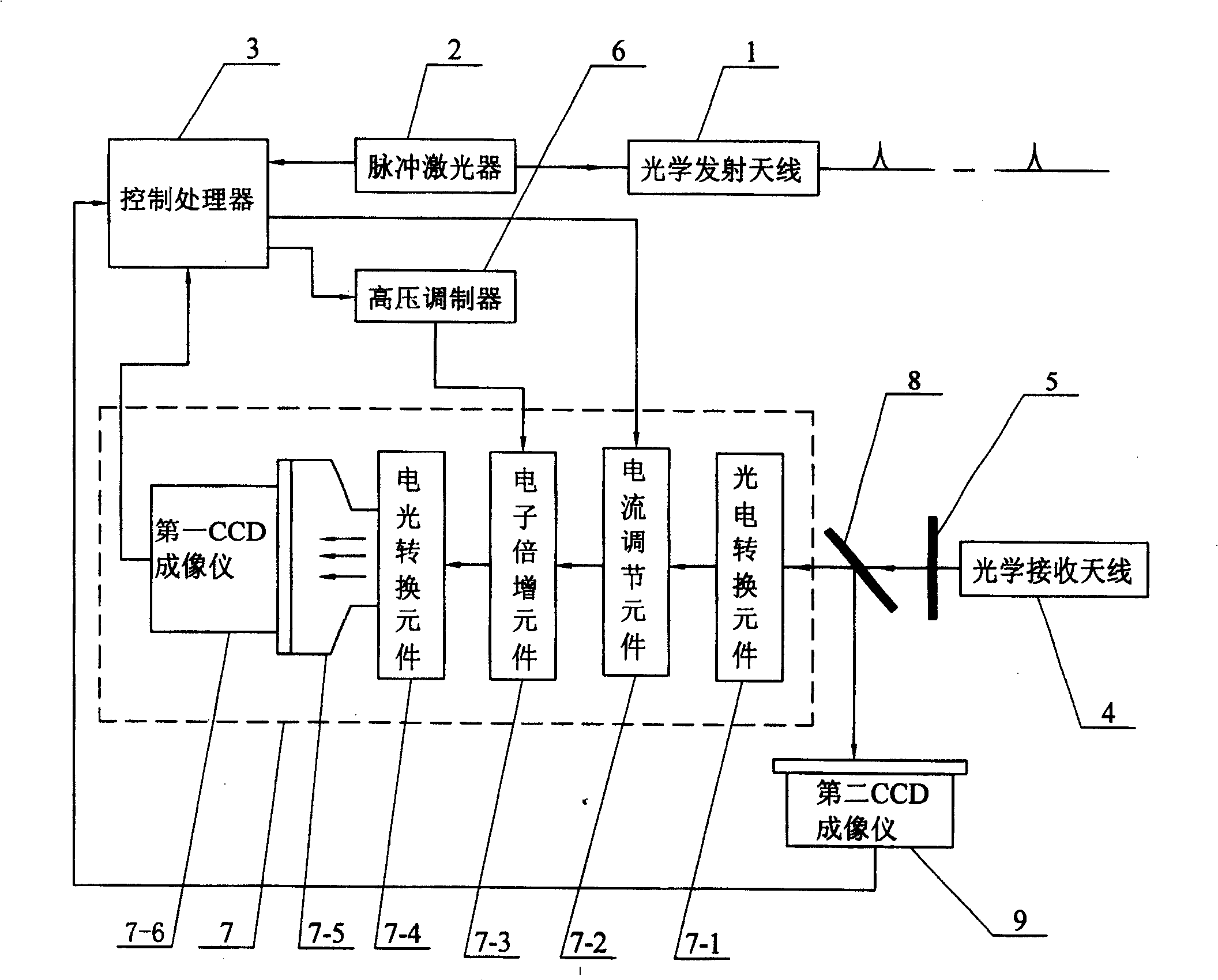
[0007] Specific implementation mode one: see figure 1 The gain-modulated pulsed imaging laser radar system of this specific embodiment is composed of an optical transmitting antenna 1, a pulsed laser 2, a control processor 3, an optical receiving antenna 4, an optical filter 5, a high-voltage modulator 6 and an intensity imager 7, The light beam emitted by the pulse laser 2 is shaped by the optical transmitting antenna 1 and irradiated on the target, and the light beam reflected by the target is shaped and converged by the optical receiving antenna 4 and reaches the optical input end of the optical filter 5. The light from the optical filter 5 The light beam output by the output end is incident on the optical input end of the intensity imager 7, and the intensity imager 7 obtains a target intensity image whose intensity value is proportional to the round-trip time of the light pulse, and the output end of the intensity imager 7 is connected to the control processor 3 One image...
specific Embodiment approach 2
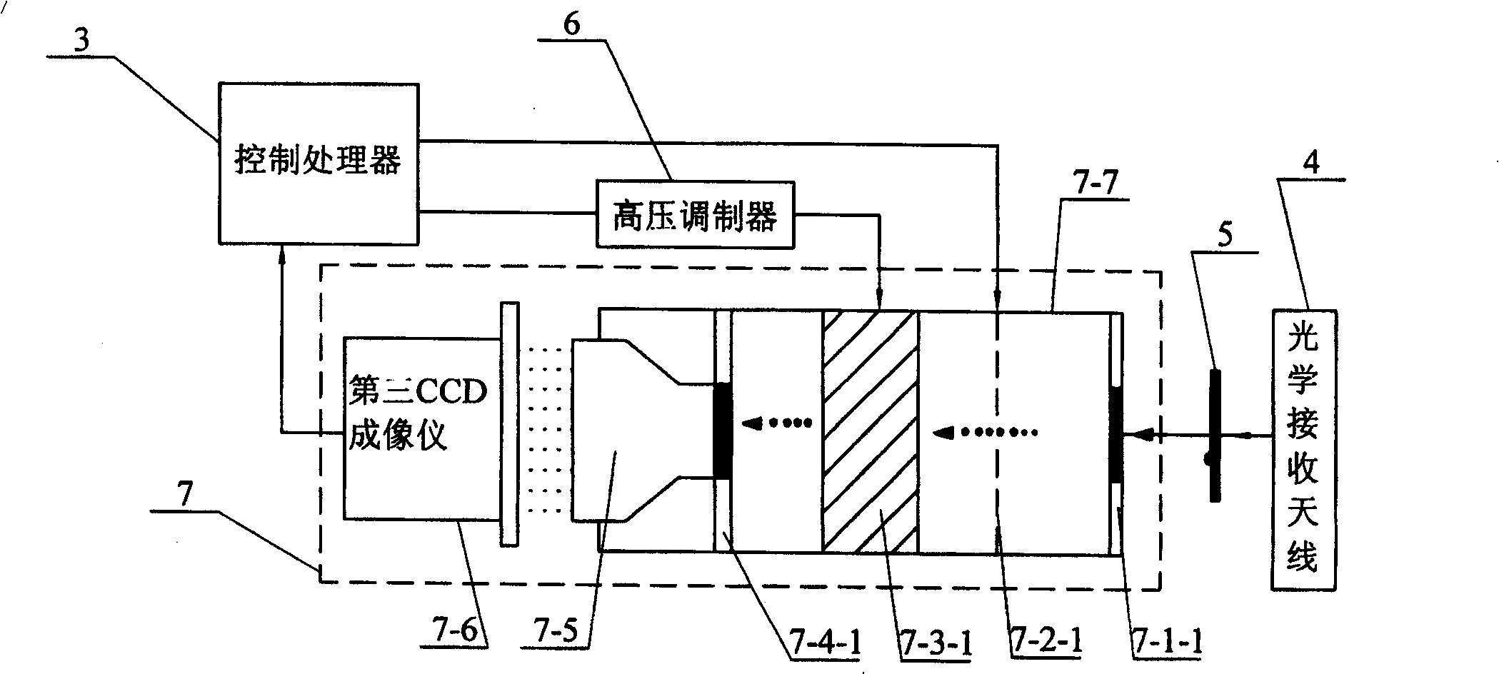
[0010] Specific implementation mode two: see figure 1 and figure 2 The difference between this specific embodiment and specific embodiment 1 is: the intensity imager 7 selects a gate-type ICCD imager, and the gate-type ICCD imager includes a photocathode that can be used as a photoelectric conversion element 7-1 7-1-1, grid 7-2-1 that can be used as current regulating element 7-2, voltage adjustable microchannel plate that can be used as electron multiplication element 7-3 7-3-1, can be used as The image intensifier 7-7 formed by the fluorescent screen 7-4-1 of the electro-optic conversion element 7-4, the light beam obtained from the light output end of the optical filter 5 is incident on the photocathode 7-1-1 of the gate-type ICCD imager Above, the output end of the gate-type ICCD imager is connected to an image information input end of the control processor 3, and the monotonously variable modulation signal output end of the high-voltage modulator 6 is connected to the v...
specific Embodiment approach 3
[0012] Specific implementation mode three: see figure 1 The difference between this embodiment and Embodiment 1 is that the imaging laser radar system also includes a beam splitter 8 and a second CCD imager 9, and the light beam obtained from the light output end of the optical filter 5 is split into After the sheet 8 splits the beam, a part of the light beam is incident on the light input end of the intensity imager 7, and another part of the light beam is incident on the light input end of the second CCD imager 9, and the image output end of the second CCD imager 9 communicates with the control processor 3 The other image input terminal is connected. Other compositions and connections are the same as in the first embodiment. This specific embodiment adds a CCD imager, which is used to obtain the image information before the echo pulse enters the intensifier. Compared with the specific embodiment 1, this specific embodiment can be used to simultaneously obtain the above-ment...
PUM
 Abstract
Description
Claims
Application Information
 - R&D
- Intellectual Property
- Life Sciences
- Materials
- Tech Scout
- Unparalleled Data Quality
- Higher Quality Content
- 60% Fewer Hallucinations
Browse by: Latest US Patents, China's latest patents, Technical Efficacy Thesaurus, Application Domain, Technology Topic, Popular Technical Reports.
© 2025 PatSnap. All rights reserved.Legal|Privacy policy|Modern Slavery Act Transparency Statement|Sitemap|About US| Contact US: help@patsnap.com


