
Dual-locomotive and dual-stage screw refrigerating compressor set

A technology of compressor units and compressors, which is applied to refrigerators, compressors, compressors with cascaded work, etc., can solve the problems of paralysis of the refrigeration system, complicated installation and connection, and large motor power configuration of low-voltage stage compressors. Achieve the effect of reducing the power of the oil pump motor, facilitating flexible control, and saving energy in the operation of the equipment

Active Publication Date: 2008-12-31
武汉新世界制冷工业有限公司
View PDF5 Cites 9 Cited by
  • Summary
  • Abstract
  • Description
  • Claims
  • Application Information

AI Technical Summary

Problems solved by technology

[0008] Since the low-pressure stage compressor and the high-pressure stage compressor in the above-mentioned two-stage screw refrigeration compression dispersion system are respectively equipped with independent oil circuit circulation systems, the two sets of oil circuit circulation systems overlap, and generally use dual oil pumps, one for operation and one for standby. Due to the forced oil supply and the excessively large motor power configuration of the low-pressure compressor, its installation and connection are complicated, bulky and bulky. At the same time, there are many components, and the entire system can only be installed in a scattered manner, which will inevitably occupy a large building area. Equipment investment costs and land construction costs have increased significantly
Moreover, if a compressor fails in the bulk system, the entire refrigeration system will be paralyzed.

Method used


Image

  • Dual-locomotive and dual-stage screw refrigerating compressor set
  • Dual-locomotive and dual-stage screw refrigerating compressor set
  • Dual-locomotive and dual-stage screw refrigerating compressor set

Examples


Embodiment Construction

[0030] Below in conjunction with accompanying drawing and specific embodiment the present invention is described in further detail:

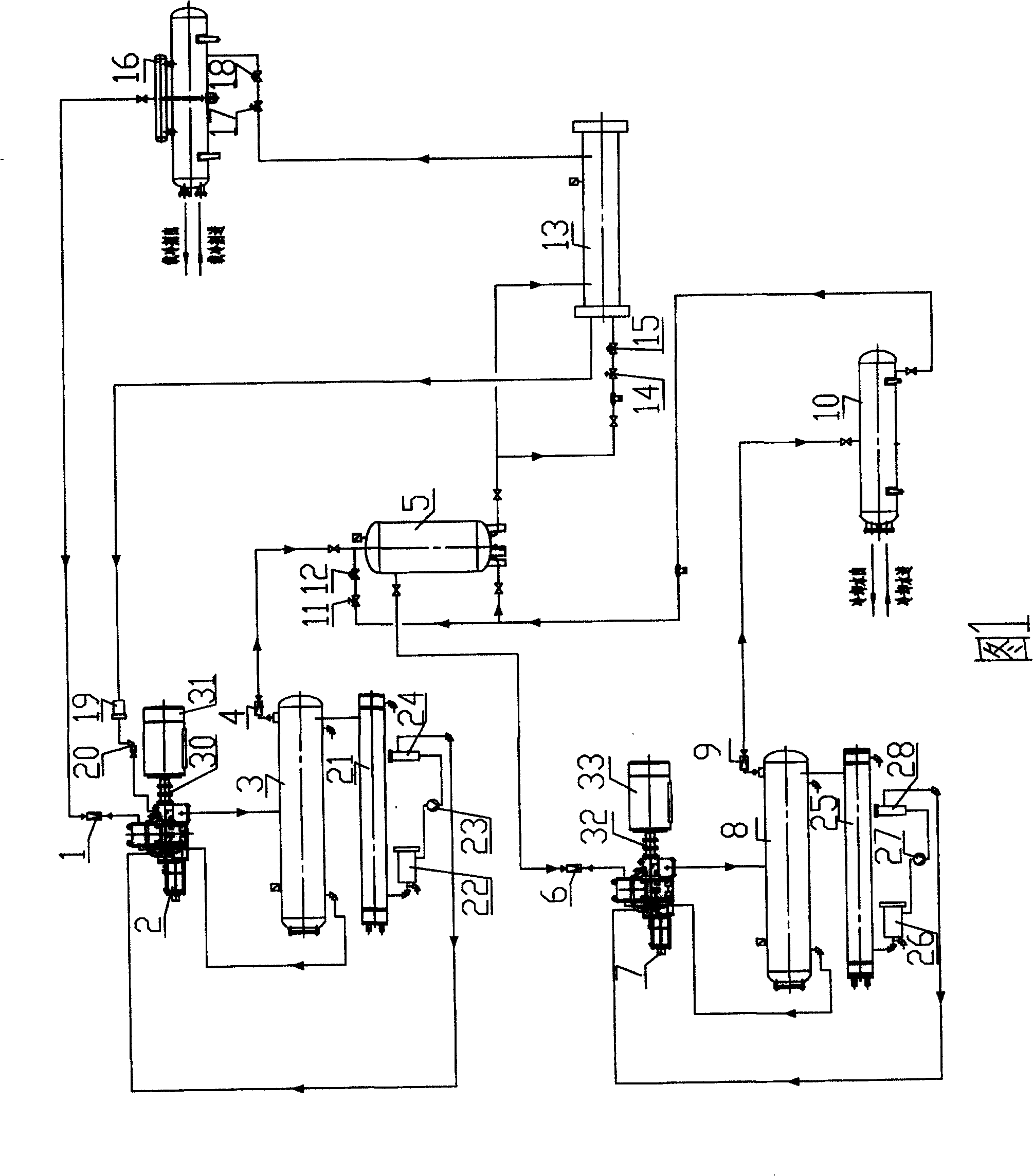
[0031] The structure and working process of the traditional two-stage screw refrigeration compression dispersion system shown in Fig. 1 have been described in detail in the previous section of the background technology, and will not be repeated here.

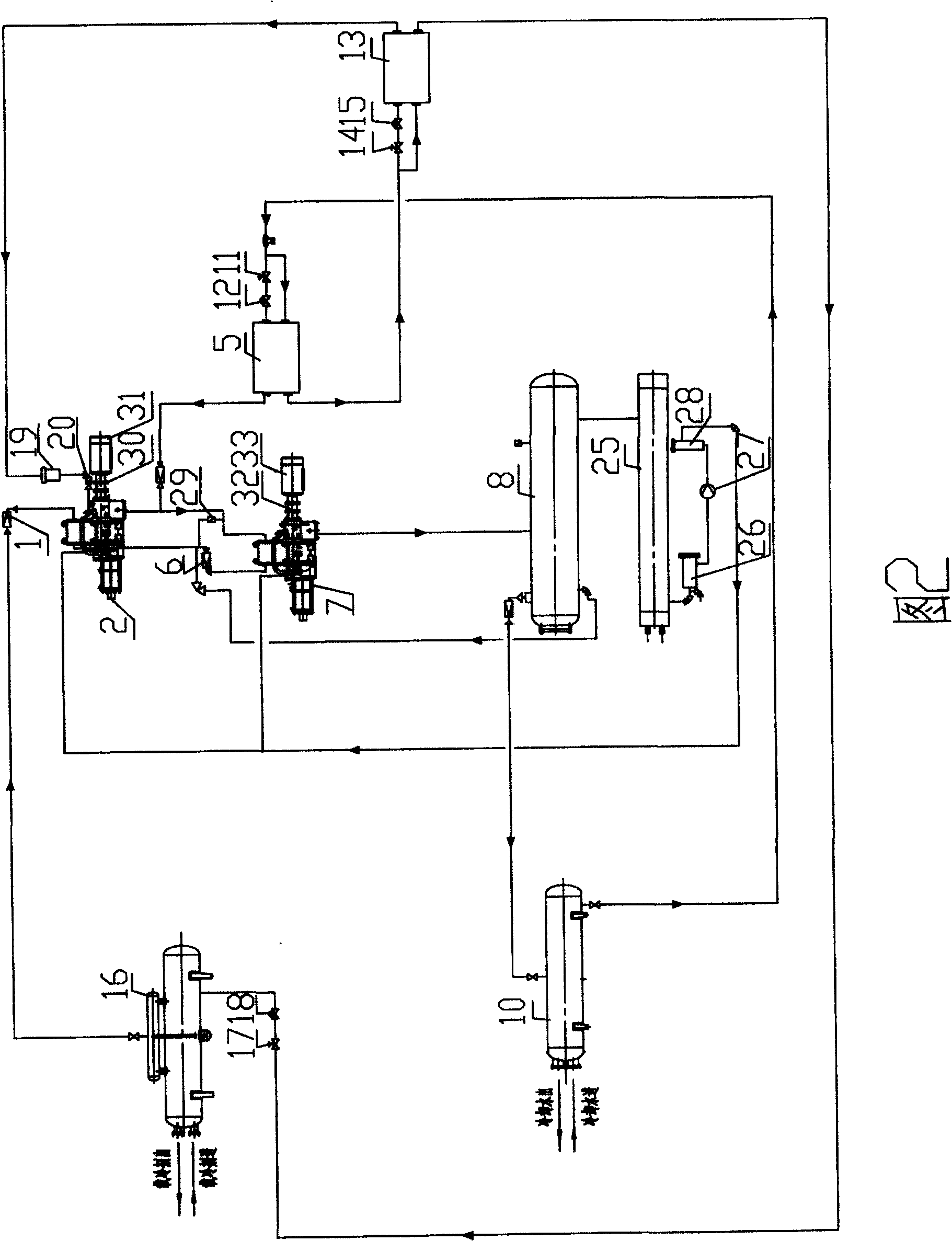
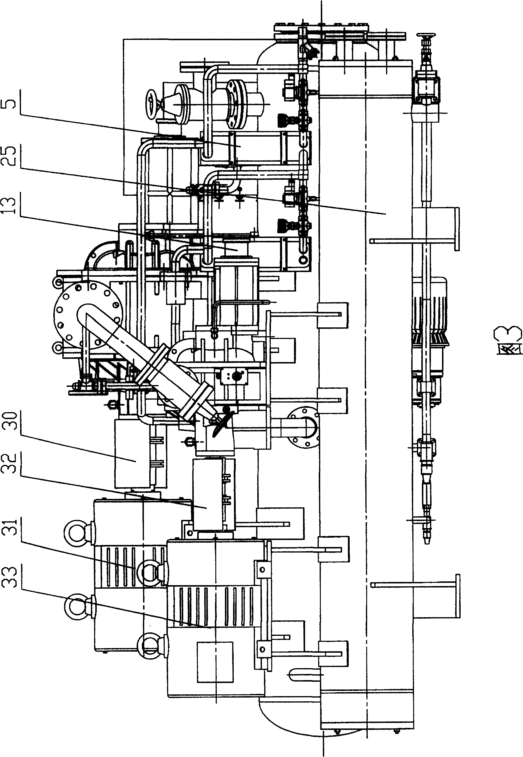
[0032] The two-machine two-stage screw refrigeration compressor unit shown in Figures 2 to 4 mainly consists of a low-pressure stage compressor 2, a high-pressure stage compressor 7, a horizontal oil separator 8, an oil cooler 25, and an oil compressor connected through pipelines and valves. Coarse filter 26, oil pump 27, olein filter 28, intercooler 5, low-pressure stage economizer 13, and microcomputer control box 34 etc. are composed. The low-pressure stage compressor 2 and its coupling 30 and the driving motor 31 are arranged on the oil separator 8, the high-pressure stage compressor 7 and its...


PUM


Abstract

This kind of double-machine, double-screw cold compressor system mainly consists of evaporator, compressor in low-pressure zone, compressor in high-pressure zone, recycle unit to separate oil, condenser, condenser in the middle part, low-pressure economizer system. There is no inspiration passage between evaporator and compressor in high-pressure zone. The vent on compressor in low-pressure zone connects directly with the air entry on compressor in high-pressure. Compressors low-pressure zone and high-pressure zone share one recycle unit of oil separation. Condenser, condenser in the high-pressure zone, economizer system in low-pressure zone and evaporator are linked up in that order so that part of the refrigerating medium can absorb enough heat to boil and evaporate, provide vapor at a temperature near saturation to the compressor in the high-pressure zone and supply vapor to the compressor in the low-pressure zone. Meanwhile, the other part of refrigerating medium will be passed to the evaporator after being cooled twice for recycle. It is the best choice among the products of refrigeration and deepfreeze in low temperature because of its tidy and compact structure, reasonable layout, small size, stable and credible operation, low cost and high cooling performance.

Description

technical field [0001] The invention relates to a screw type refrigeration compressor unit, in particular to a double-machine two-stage screw type refrigeration compressor unit. Background technique [0002] The single-stage screw refrigeration compressor unit is mainly composed of a screw refrigeration compressor, an oil separator, an oil cooler, an oil filter, an oil pump and a circulation pipeline, etc., and together with an evaporator and a condenser, they form a single-stage screw refrigeration compressor. system. The screw refrigeration compressor draws refrigerant vapor from the evaporator, compresses the refrigerant vapor, and discharges the pressurized vapor from the oil separator to the condenser. In the condenser, the refrigerant vapor exchanges heat with the cooling medium and is condensed into a liquid with a certain pressure. The liquid at a certain pressure enters the evaporator after being lowered in temperature and pressure by the throttling device. In th...

Claims


Application Information

Patent Timeline
Patent Type & Authority Patents(China)
IPC IPC(8): F25B7/00F25B1/10
Inventor 李军刘聪丁杰霍正齐
Owner 武汉新世界制冷工业有限公司
Learn More