
LED device with temp. control function

A technology for light-emitting diodes and temperature control, which is applied in lighting devices, cooling/heating devices for lighting devices, lighting and heating equipment, etc., and can solve the problems of burning light-emitting diodes and poor heat dissipation efficiency.

Inactive Publication Date: 2008-12-31
POLYTRONICS TECH
View PDF9 Cites 0 Cited by
  • Summary
  • Abstract
  • Description
  • Claims
  • Application Information

AI Technical Summary

Problems solved by technology

However, in order to increase the brightness, there is still the possibility of poor heat dissipation efficiency if multiple LEDs are used to form a light source module or a high-efficiency LED device with a large chip, and there is a possibility of burning the LEDs.

Method used


Image

  • LED device with temp. control function
  • LED device with temp. control function
  • LED device with temp. control function

Examples


Embodiment Construction

[0021] The present invention will be described according to the accompanying drawings to clearly reveal the technical features of the present invention.

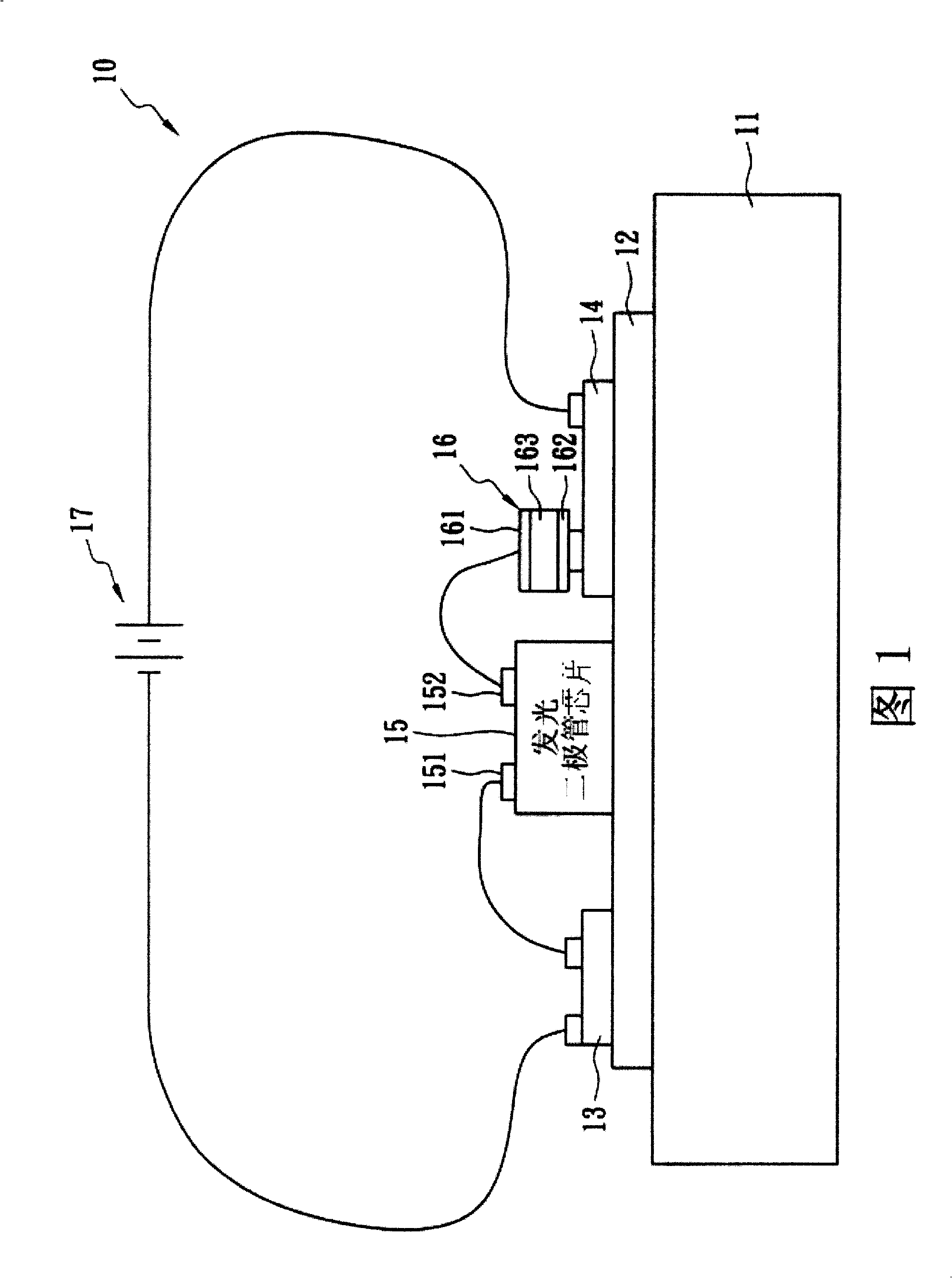
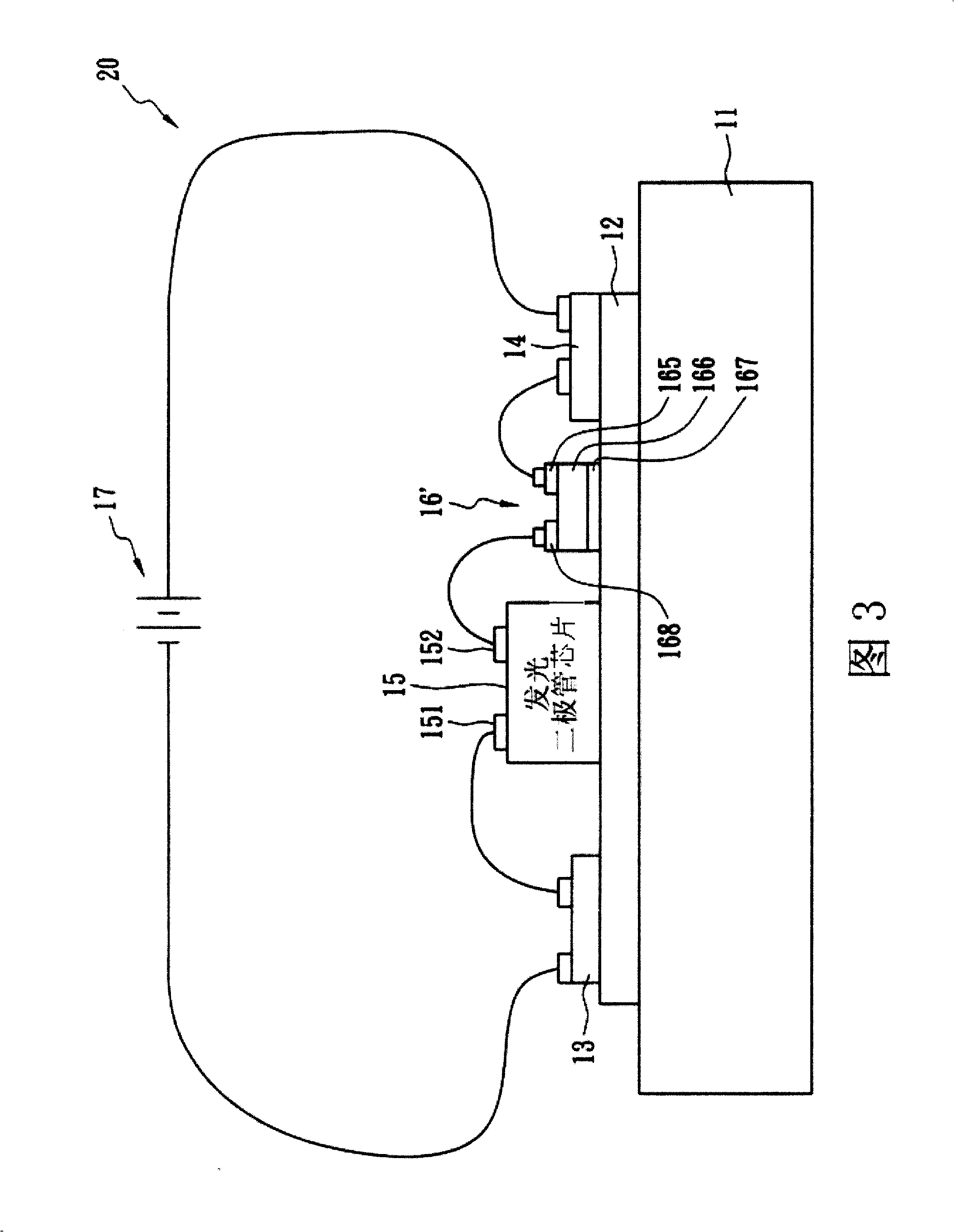
[0022] FIG. 1 is a schematic diagram of a light emitting diode device with a temperature control function according to a first embodiment of the present invention. An LED device 10 with temperature control function includes a heat sink 11 , a heat conduction layer 12 , a first electrode 13 , a second electrode 14 , an LED chip 15 and a temperature control element 16 . The light-emitting diode chip 15, the first electrode 13 and the second electrode 14 are arranged on the surface of the heat-conducting layer 12, and the other side of the heat-conducting layer 12 is in contact with the heat sink 11, so that the light-emitting diode The chip 15 dissipates heat. Briefly, the heat conducting layer 12 and the heat sink 11 carry the LED chip 15 and are used for heat dissipation when it emits light (for example, white light).

[0...


PUM


Abstract

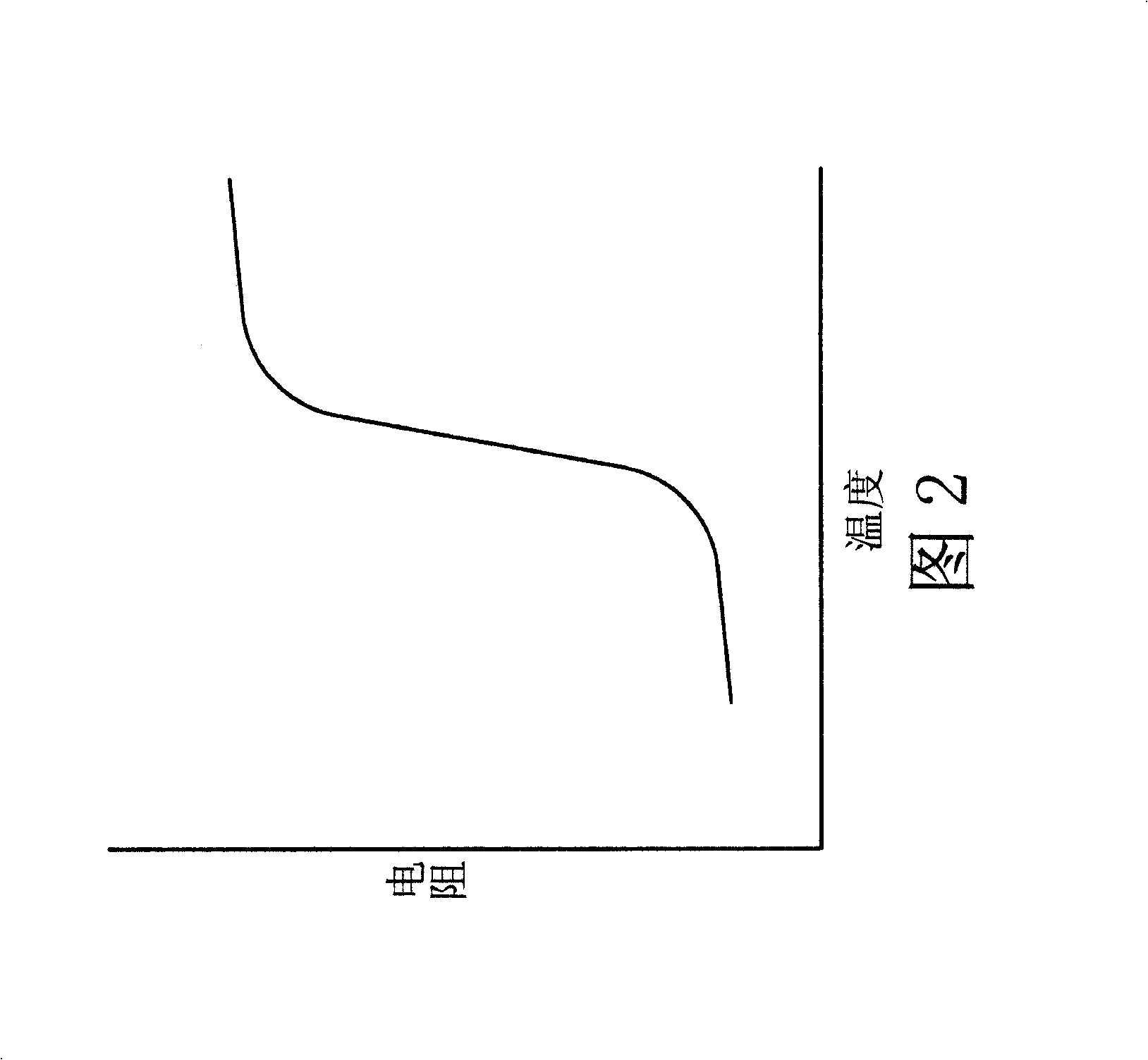
The invention discloses a light-emitting diode device with temperature control function, which includes a light-emitting diode chip, a heat sink, a heat conduction layer and a temperature control element. The heat sink and the heat conduction layer arranged on its surface carry the LED chip, and dissipate heat for the LED chip when the LED chip is connected to a power source (ie, when it emits light). The temperature control element is electrically connected in series between the light-emitting diode chip and the power supply, has a positive temperature coefficient, and is less than 3 centimeters away from the light-emitting diode chip. The heat conduction layer may be composed of polymer dielectric material, and the thermal conductivity is greater than 1.0 W / mK (at room temperature of 25° C.).

Description

technical field [0001] The invention relates to a light-emitting diode (LED) device, in particular to a light-emitting diode device with temperature control functions such as over-temperature protection or temperature adjustment. Background technique [0002] In recent years, white light-emitting diodes are the most promising emerging products that have attracted global attention. It has the advantages of small size, low power consumption, long life and fast response, and can solve many problems that incandescent bulbs were difficult to overcome in the past. [0003] At present, countries such as Europe, America and Japan are actively developing white light-emitting diodes as new light sources for lighting in this century based on the consensus of energy conservation and environmental protection. In addition, many countries currently rely on imports of energy, making its development in the lighting market extremely valuable. According to expert evaluation, if Japan replace...

Claims


Application Information

Patent Timeline
Patent Type & Authority Patents(China)
IPC IPC(8): H01L33/00H01L23/34F21V29/00F21V29/50F21V29/85H01L33/64
CPCH01L2224/48091H01L2224/48137H01L2224/73265H01L2924/00014
Inventor 王绍裘游志明
Owner POLYTRONICS TECH
Learn More