Narrow profile furrow opener capable of operating at high speed

A technology of openers and furrows, applied in the field of openers, can solve problems such as increased cost and maintenance, cannot be completely solved, and blocked.

Inactive Publication Date: 2009-01-07
DEERE & CO
View PDF10 Cites 0 Cited by
  • Summary
  • Abstract
  • Description
  • Claims
  • Application Information

AI Technical Summary

Problems solved by technology

Also, the planting trolley wheels in some currently available openers (see O for prior art examples of Figs. 11 and 12) may actually constitute an elongated shelf in the side of the furrow (F) or raised (R), especially when operating relatively deeply, and the seeds may be on the raised rather than at the bottom of the furrow
Another problem arises when soil disturbed by unwanted shelving or heaving operations falls into the bottom of the furrow and interferes with seed placement
[0006] Various kinds of bounce baffles or seed securing devices such as those shown in US Patents US5092255; US5673638 and US5918557 have been proposed to limit bounce or to secure the material (seed) in the furrow, but this results in increased components, overhead and Repairs increased and sometimes didn't fully resolve issues caused by bounces and bumps
Some runner configurations reduce frame ground clearance, but can be a cause of hindrance, especially in fields with high trash content

Method used


Image

  • Narrow profile furrow opener capable of operating at high speed
  • Narrow profile furrow opener capable of operating at high speed
  • Narrow profile furrow opener capable of operating at high speed

Examples


Embodiment Construction

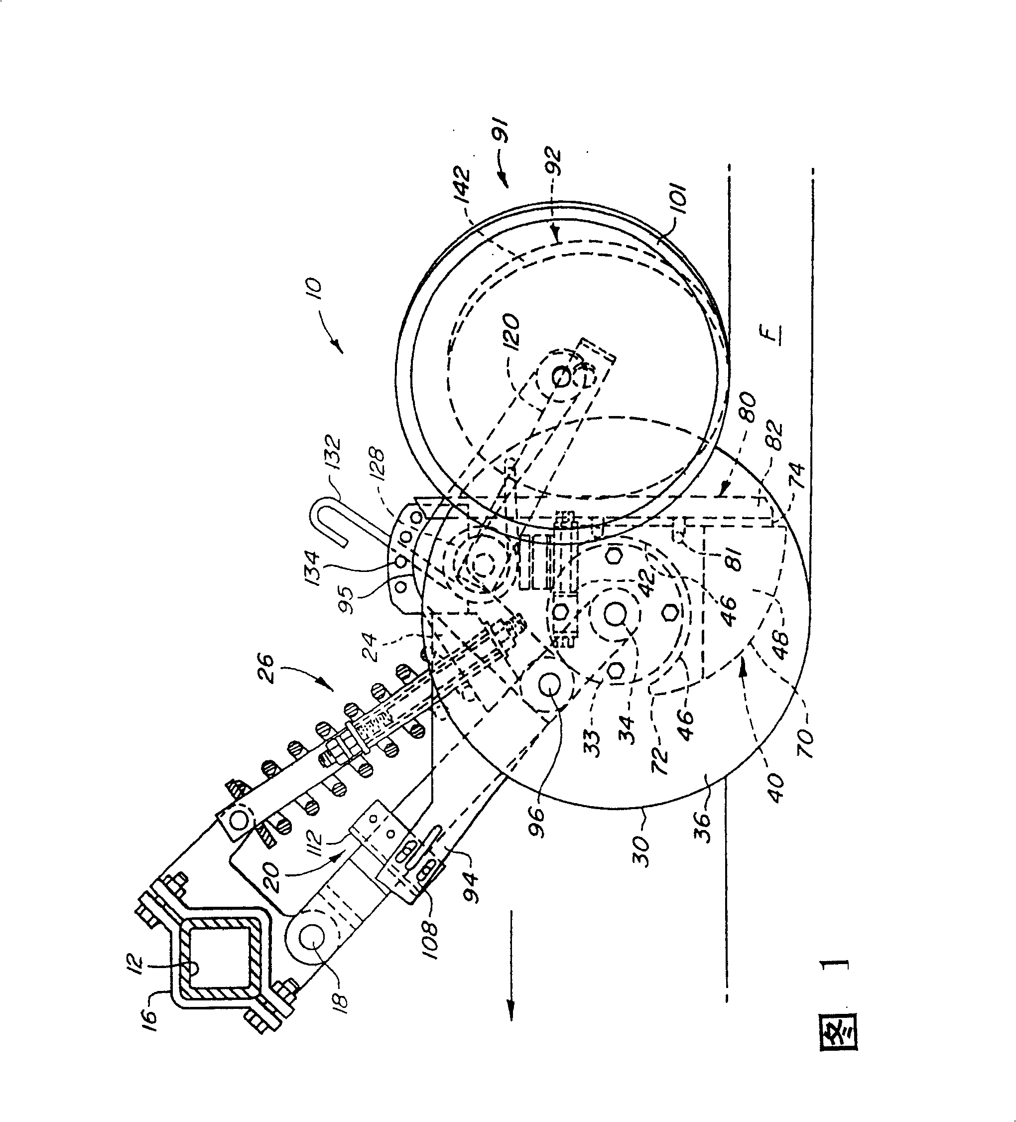
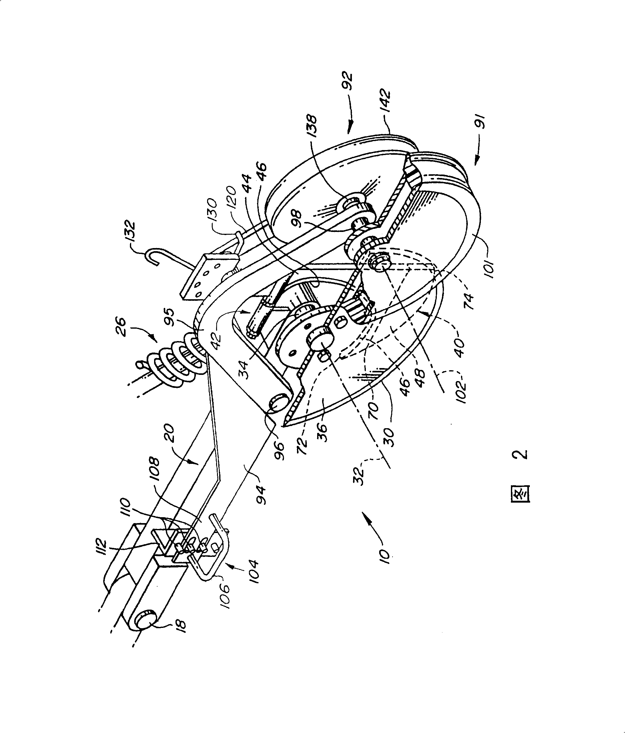
[0036] Referring now to FIG. 1 , there is shown an opener assembly 10 which is attached to a laterally extending frame tube or universal frame 12 of an implement, such as a grain drill, for forward movement over the ground (arrow direction). ) movement to place material such as seed and / or fertilizer into a furrow F formed by the device 10. A bracket 16 is connected to the universal frame 12 and includes a lower pivot 18 supporting the upper front end of the tie rod 20 . A spring support 24 is attached near the lower rear end of the tie rod 20, and a compression spring and tension link assembly 26 is biased downwardly at the rear end and when the universal frame 12 is moved from the field working position shown in FIG. When swinging to a transport position, the downward movement of the pull rod 20 about the pivot 18 is limited.

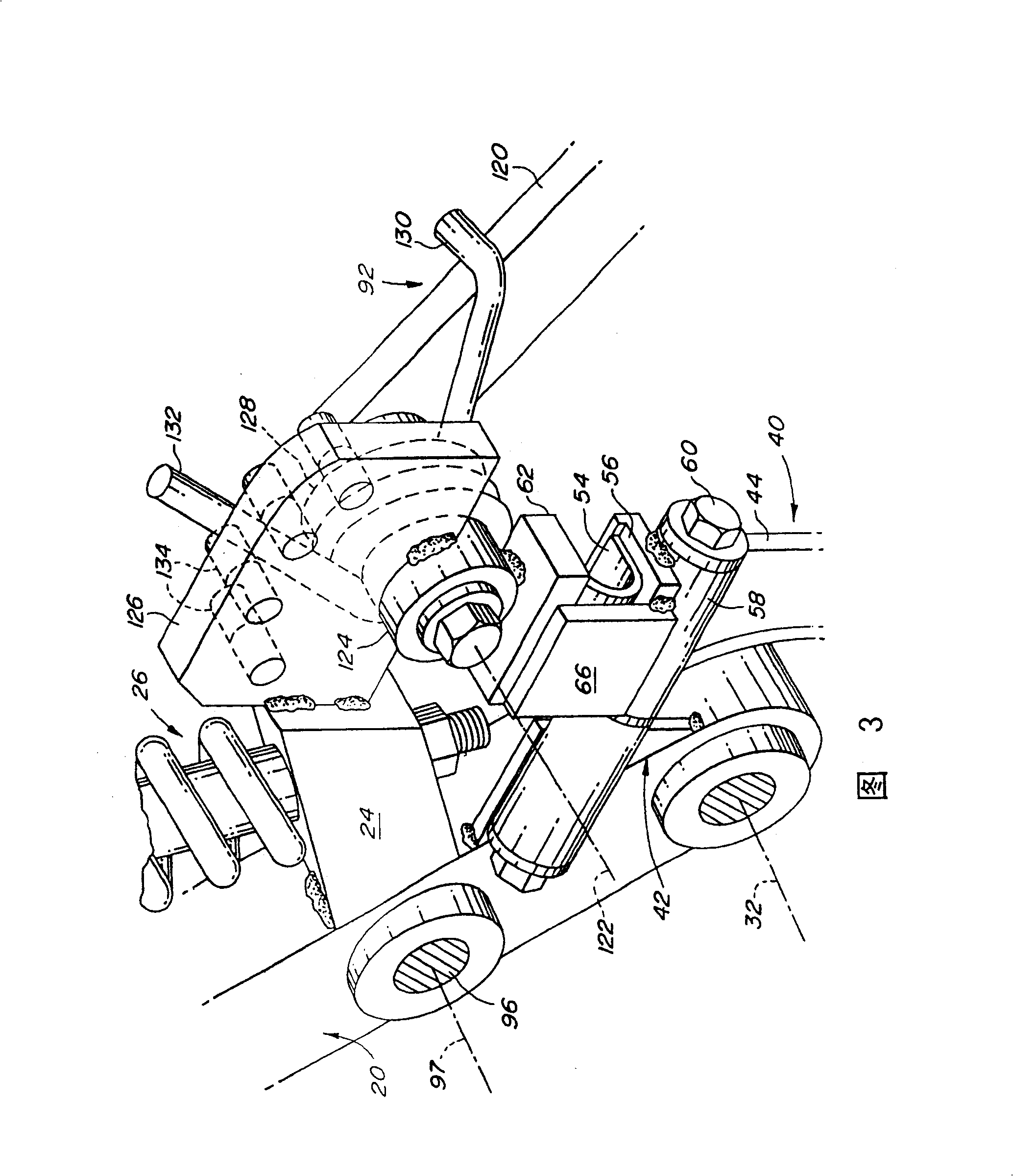
[0037] A disc 30 is supported for rotation about an axis 32 by a hub 33 and a support 34 at the lower rear end of the tie rod 20 . Axis 32 is sligh...


PUM


Abstract

The opener comprises a single opener disc rotatably supported on a tie rod and inclined at about 5 degrees relative to the direction of advancement, thereby defining a sheltered area behind the rear surface of the disc. The material placement skid and delivery tube are supported adjacent the rear surface, substantially entirely within the sheltered area of ​​the disc and having a contour that conforms to the contour of the furrow. The shoe and the exit portion of the conduit are also located within the circumference of the disc so as to be protected. The duct has an upper part with a circular cross-section which changes to an elliptical cross-section towards the outlet in order to remain within the sheltered area while maintaining a high delivery performance. First and second ground contacting wheels are supported on either side of the disc to push the soil downwardly behind the outlet of the delivery tube immediately after the material has been laid down. The immediate action of the soil caused by the closely spaced runners pushes material to the bottom of the furrow and prevents material from bouncing to maintain a more consistent material depth. A short, lightweight runner arm on the rear side of the opener disc reduces unit length and weight, and the runner biased toward the soil is primarily spring action rather than weight for better terrain Respond quickly. The runner on the front side of the inclined opener disc is supported behind the disc axis by an arm arrangement which provides depth adjustment from the front end of the tie rod. The wheel is inclined in roughly the same direction as the disc to dispose of the residue.

Description

technical field [0001] This invention relates to furrow openers for grain drills, planters or similar agricultural implements which deposit material such as seed or manure into a furrow and then close the furrow. Background technique [0002] A furrower device for placing seeds or fertilizers into a furrow, such as shown in U.S. Patent No. 4,760,806 to Bigbee et al., includes an inclined disc (swash plate) and a seed boot device, Where the swash plate has a depth control wheel adjacent the front thereof, the seeding skid assembly includes a seed guide on the rear side of the swash plate. The rotary wheel provides depth adjustment, clears the front of the swashplate, and limits soil rise and sides of the swashplate. One or more closing or pressing wheels follow the swash plate to move the soil and close the furrow, thereby covering the material emerging from the seed tube. Such openers limit soil disturbance, but usually only part of the planting shoe or wheel works the soi...

Claims


Application Information

Patent Timeline
Patent Type & Authority Patents(China)
IPC IPC(8): A01C7/20A01B13/02A01C5/06
CPCA01C5/068A01C5/064
Inventor I·温丁L·P·菲尔古森
Owner DEERE & CO
Why Eureka
Try Eureka