High temperature corrosion resisting low NOx vortex burning device

A high-temperature corrosion and combustion device technology, which is applied in the direction of burning with various fuels, burners, and burning with block fuels and liquid fuels, can solve problems such as high-temperature corrosion, reduce the generation of NOx, prolong the transit time, The effect of suppressing the production of NOx

Inactive Publication Date: 2009-02-25
HARBIN INST OF TECH
View PDF6 Cites 0 Cited by
  • Summary
  • Abstract
  • Description
  • Claims
  • Application Information

AI Technical Summary

Problems solved by technology

[0003] The purpose of the present invention is to provide a low NOx swirl combustion device that prevents high temperature corrosion in order to solve the problem of high temperature corrosion while reducing NOx emissions in large pulverized coal boilers that currently use swirl burners

Method used


Image

  • High temperature corrosion resisting low NOx vortex burning device
  • High temperature corrosion resisting low NOx vortex burning device
  • High temperature corrosion resisting low NOx vortex burning device

Examples


specific Embodiment approach 1

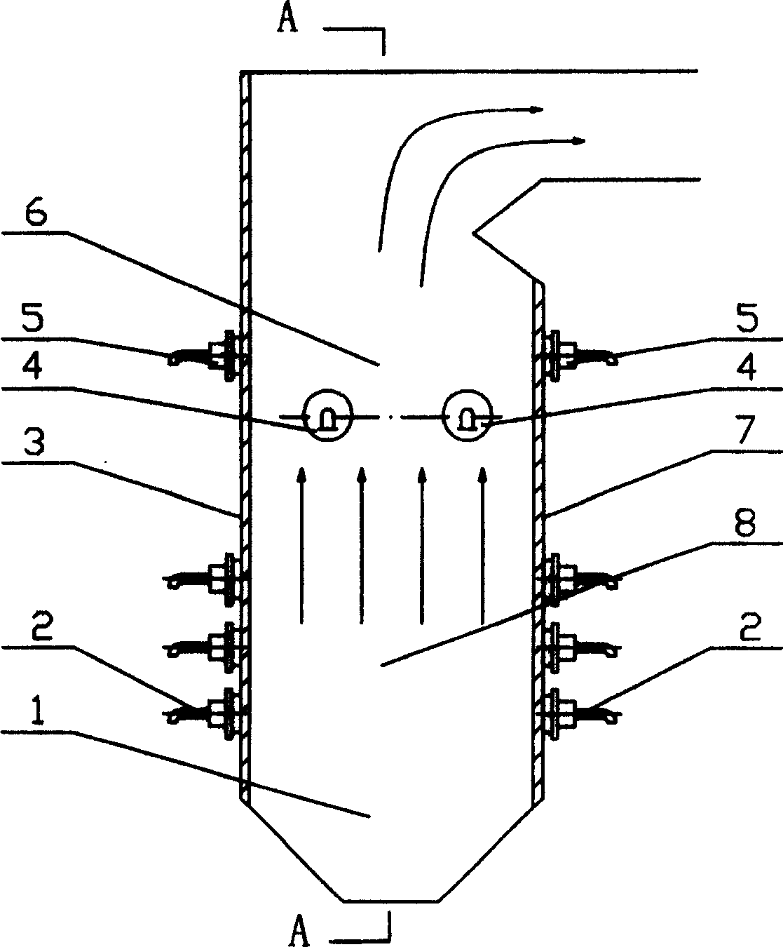
[0007] Specific implementation mode one: (see figure 1 , Figure 4 ) This embodiment consists of a furnace 1, a plurality of central powder feeding swirl pulverized coal burners 2, a front wall 3, a side wall OFA (overburned air) nozzle 4, a swirling OFA (overfired air) nozzle 5, and a burnout zone 6. The rear wall 7, the main combustion area 8 and two side walls 9; the furnace 1 is formed between the front wall 3, the rear wall 7 and the two side walls 9, and the side wall OFA (overfired air) nozzle 4 is set in the furnace The upper part of the two side walls 9 in 1, the furnace 1 area where the pulverized coal burner 2 is located is the main combustion zone 8 in the center of the side wall OFA (burned out air) nozzle 4, and the side wall OFA (burned out air) The furnace 1 area where the wind) nozzle 4 and the swirl OFA (overburned air) nozzle 5 are located is the burnout zone 6, and a plurality of central powder-feeding swirl pulverized coal burners 2 are respectively arran...

specific Embodiment approach 2

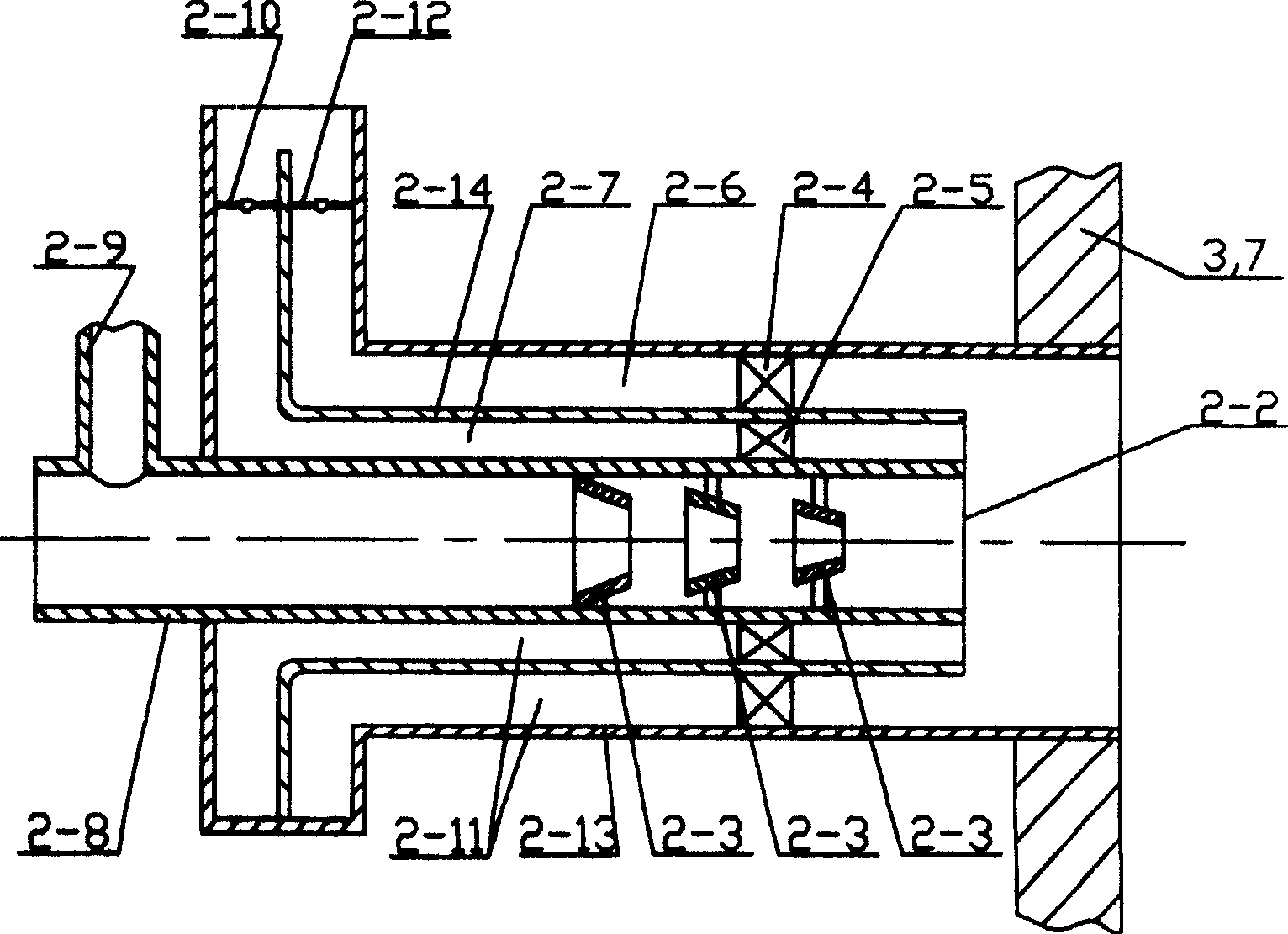
[0008] Specific implementation mode two: (see figure 2 ) The central powder feeding swirl pulverized coal burner 2 of the present embodiment consists of a burner 2-2, three conical separation rings 2-3, an outer swirl 2-4, an inner swirl 2-5, a primary Air duct 2-8, powder delivery pipeline 2-9, inner air door baffle 2-10, outer air door baffle 2-12, burner shell 2-13 and barrel-shaped partition 2-14, the burner shell The body 2-13 is fixedly connected with the front wall 3 or the rear wall 7, the primary air duct 2-8 is arranged at the center of the burner housing 2-13, and the primary air duct 2-8 is located in the burner housing 2-13 One end is the burner 2-2, the powder conveying pipeline 2-9 is arranged on the outside of the burner housing 2-13, the powder conveying pipeline 2-9 is fixedly connected with the primary air pipe 2-8, and the primary air pipe 2-8 is provided with There are three conical separation rings 2-3, and the diameters of the three conical separation ...

specific Embodiment approach 3

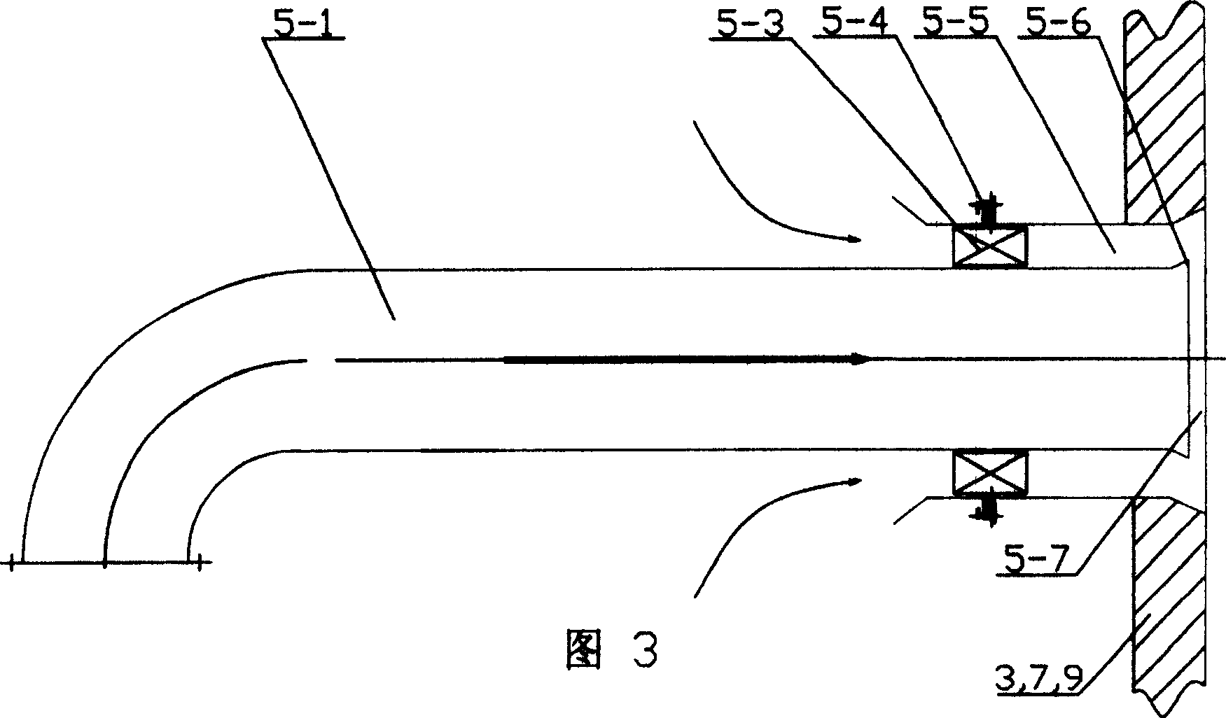
[0009] Specific embodiment three: (see Fig. 3) the swirl OFA (overburned air) nozzle 5 of the present embodiment is composed of a central secondary air duct 5-1, a swirler 5-3, a damper baffle plate 5-4, and a secondary air duct 5-1. The air channel 5-5 is composed of the central secondary air nozzle 5-6 and the secondary air nozzle 5-7. The central secondary air channel 5-1 is fixed on the front wall 3, the rear wall 7 or the side wall 9, and the secondary air The spout 5-7 is arranged on the side of the central secondary air spout 5-6 of the central secondary air duct 5-1, and a cyclone 5 is fixed between the secondary air spout 5-7 and the central secondary air duct 5-1 -3, the damper baffle plate 5-4 is arranged on the outside of the secondary air nozzle 5-7 on one side of the cyclone 5-3, and a secondary air outlet 5-7 is formed between the secondary air outlet 5-7 and the central secondary air duct 5-1. Secondary air duct 5-5. The airflow entering the central secondary ...


PUM


Abstract

The present invention relates to a low NOx cyclone combustion equipment capable of preventing high-temperature corrosion. It is characterized by that the invented side wall OFA nozzles are respectively set on the upper portion of two side walls in the furnace cavity interior, the furnace cavity zone where the side wall OFA nozzle lower-side central powder-feeding cyclone coal powder combustor is placed is main combustion zone, the furnace cavity zone where the side wall OFA nozzle and cyclone OFA nozzle are placed is burning zone, several central powder-feeding cyclone coal powder combustors are respectively set on the front and rear walls of main combustion zone side, and the cyclone OFA nozzles are respectively set on the front and rear walls of burning zone side. When the coal powder is combusted, it can further inhibit the formation of NOx, can reduce discharge of NOx by above 80%.

Description

technical field [0001] The invention relates to a combustion device, in particular to a combustion device using pulverized coal as fuel. Background technique [0002] In the large-capacity power plant boilers operating in my country, the problem of high-temperature corrosion is becoming more and more serious. After the water-cooled wall undergoes high-temperature corrosion, the wall thickness and strength will decrease, which will easily cause tube burst and leakage, endangering the safe operation of the boiler. The main cause of high temperature corrosion is the presence of a reducing atmosphere near the corroded pipe wall. In recent years, with the continuous improvement of the country's NOx emission requirements for power plant boilers, many large-capacity power plant boilers have adopted OFA (overfired air) technology, which is to achieve air classification in the furnace and reduce NOx emissions. After the application of OFA (overfired air) technology, the main combus...

Claims


Application Information

Patent Timeline
Patent Type & Authority Patents(China)
IPC IPC(8): F23C5/00F23D1/02
Inventor 李争起靖剑平陈智超秦裕琨
Owner HARBIN INST OF TECH
Why Eureka
Try Eureka