An electronic heating-cost distributor

An electronic heating and distributor technology, applied in calorimeters, circuit heating devices, instruments, etc., can solve the problems of prolonging the production process of printed circuit boards and damaging the quality.

Inactive Publication Date: 2009-03-04
DIEHL METERING SYST
View PDF4 Cites 1 Cited by
  • Summary
  • Abstract
  • Description
  • Claims
  • Application Information

AI Technical Summary

Problems solved by technology

This leads to the fact that the placement and soldering processes have to be performed at least twice consecutively, alternately, thus prolonging the production process for completing the printed circuit board
Furthermore, the second automatic machine placement process on the side of the printed circuit board on which the components have not yet been mounted has the effect of impairing the quality, because the components processed during the first automatic machine placement process are in the second automatic machine placement process. May dislodge from its adhesive and solder connections

Method used


Image

  • An electronic heating-cost distributor
  • An electronic heating-cost distributor
  • An electronic heating-cost distributor

Examples


Embodiment Construction

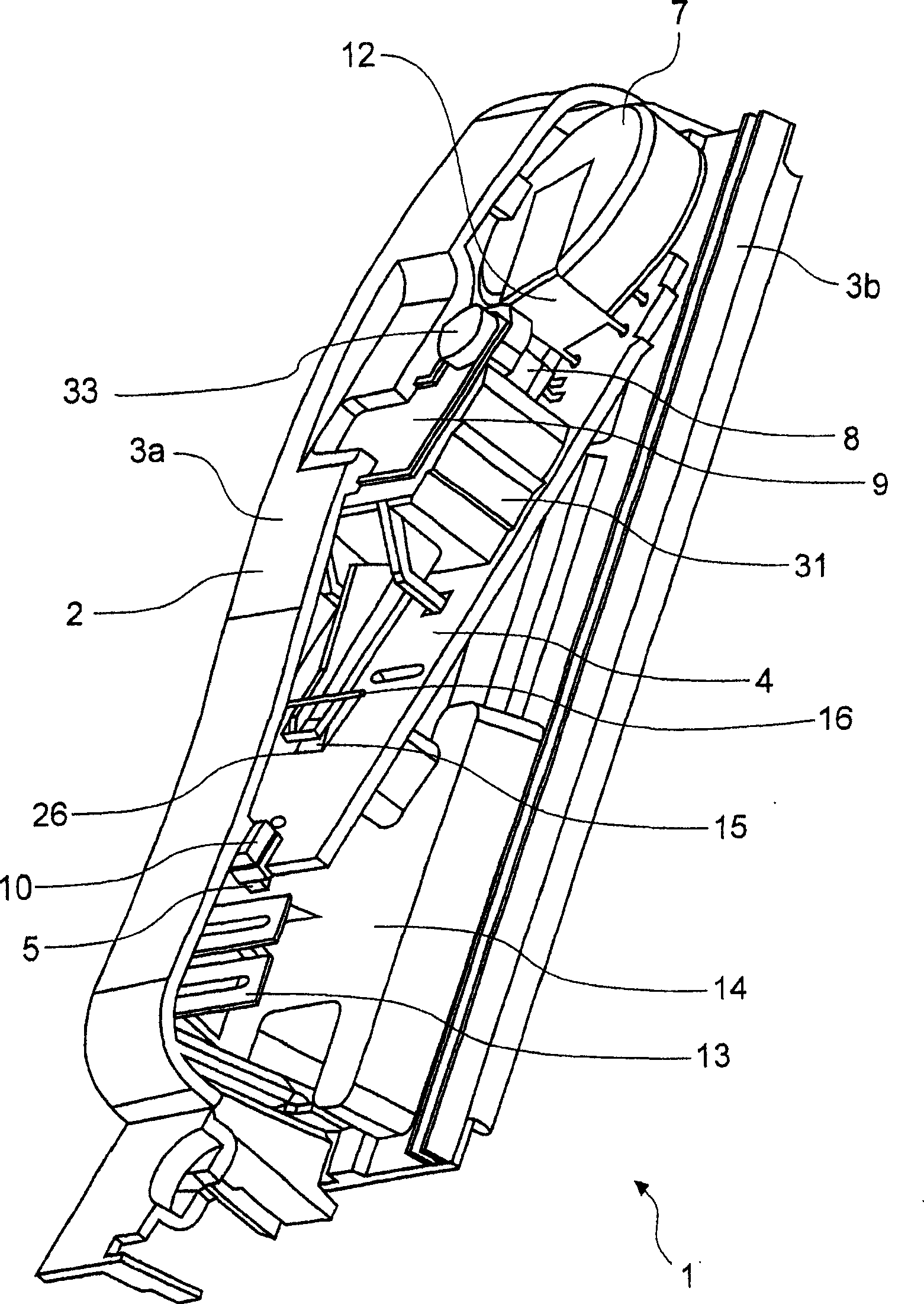
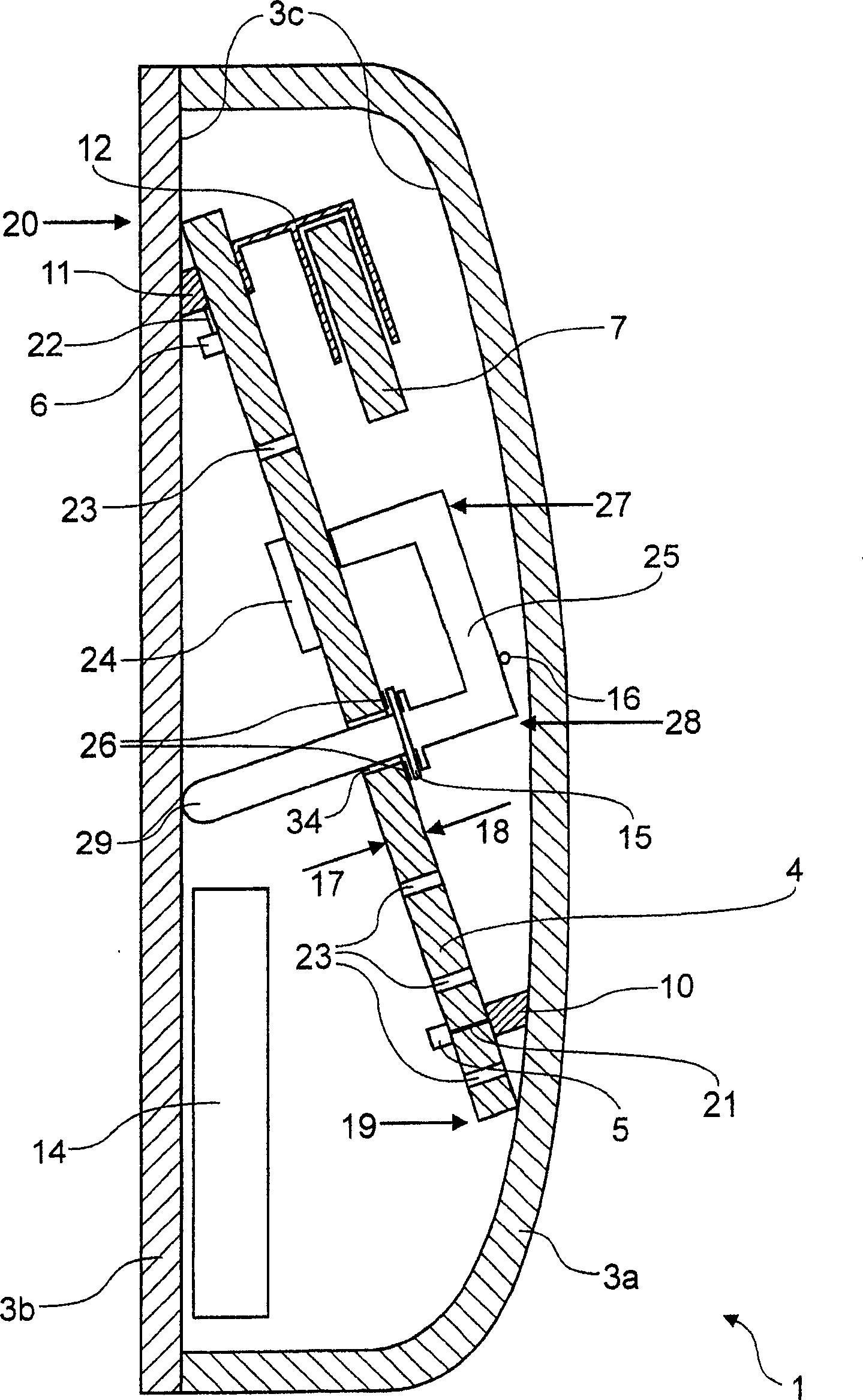
[0027] according to figure 1 The electronic heating cost allocator 1 comprises a housing 2 with a hook-shaped chamber-side housing front 3a and a rear side 3b on the heating device side for isolating the latter. Inside the housing 2, the electronic heating cost allocator 1 has a printed circuit board or circuit board 4 on which are arranged components in the form of electronics for determining the heat output by the heating device. For reading out and / or future processing of the data determined by the electronic heating cost allocator 1 , the electronic heating cost allocator 1 also includes an LC display 9 (liquid crystal display), an infrared interface 8 and a radio frequency antenna 13 .

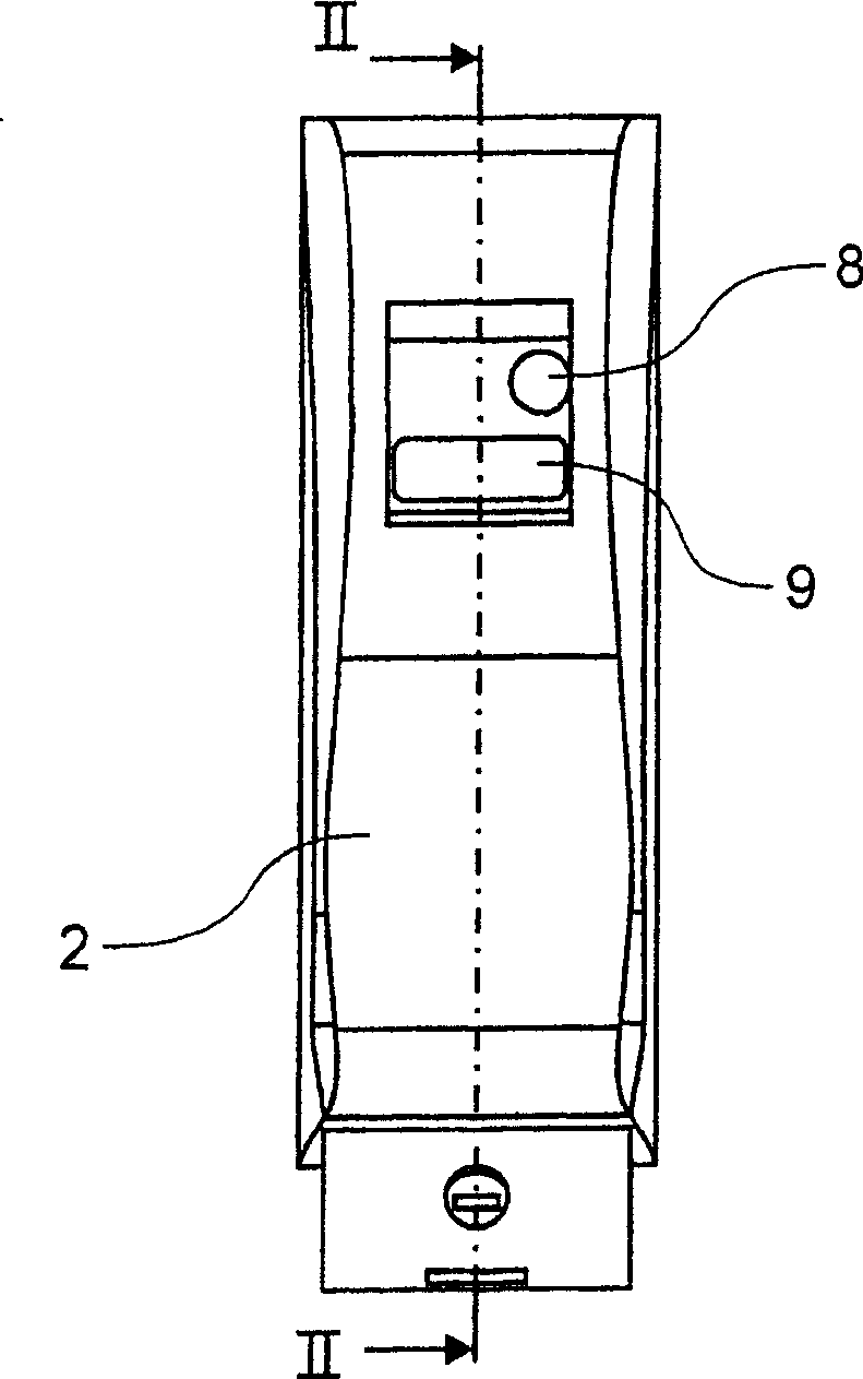
[0028] Such as image 3 As shown, the front side 3 a of the housing 2 has openings for the infrared interface 8 and the LC display 9 . The data determined by the heating cost allocator 1 can be read directly on the LC display 9 . In contrast to this, the data determined by the heating co...


PUM


Abstract

The electronic heating costs distributor (1) incorporates sensors (5, 6) which measure the temperature respectively of the room air and the heater body, and are provided with thermally conductive and elastically deformable elements (10, 11).

Description

technical field [0001] The invention relates to an electrical heating cost allocator according to the preamble of claim 1 with a printed circuit board arranged in a housing. Background technique [0002] In the case of electronic heating cost allocators for measuring the heat output by the heating device, as opposed to evaporative heating cost allocators, two temperature sensors are usually used. In this case, one sensor is used to determine the surface temperature of the heating device and the other sensor is used to determine the temperature of the room. [0003] The heating cost allocator generally has, as an integral part of its housing, a rear part which is made of a heat-conducting material and which is fastened directly to the heating device and is in a thermally conductive connection with the surface of the heating device. A front part of the housing, for example made of plastic, is arranged on said rear part and together with said rear part forms the closed housing...

Claims


Application Information

Patent Timeline
Patent Type & Authority Patents(China)
IPC IPC(8): G01K17/06G01K17/08H05K1/02H05K1/18
CPCH05K2201/0133H05K2201/09063G01K17/08H05K2201/10151H05K2201/062H05K2201/09263H05K1/18H05K1/0201H05K2201/09781H05K1/0206G01K17/06
Inventor 沃尔夫冈·维尔纳尔马克·塞巴尔德格哈德·贝克
Owner DIEHL METERING SYST
Why Eureka
Try Eureka