A backlight source module

A backlight and module technology, applied in optics, nonlinear optics, instruments, etc., can solve problems such as unfavorable heat conduction, optical diaphragm warping, large axial temperature difference of CCFL, etc., to increase heat conduction space and improve structure Compact, eliminates the effect of heat concentration

Inactive Publication Date: 2009-03-04
BEIJING BOE OPTOELECTRONCIS TECH CO LTD +1
View PDF4 Cites 0 Cited by
  • Summary
  • Abstract
  • Description
  • Claims
  • Application Information

AI Technical Summary

Problems solved by technology

[0004] 1. The bottom reflective film is pasted on the bottom plate, and the thickness is relatively large, which is not conducive to heat conduction;
[0005] 2. The distance between the lower tube wall of the CCFL and the bottom reflective film is too small, and the reflection and refraction of light energy are concentrated in this area, resulting in local concentration of heat, which is not suitable for dissipation;
[0006] 3. The number of illuminants is large, and the input current is large, the overall structure of the backlight module is compact, and there is no sufficient space for heat dissipation
[0007] The main problems caused by the above defects are: the optical film is warped and deformed due to high temperature, resulting in uneven brightness on the surface of the backlight module; the CCFL axial temperature difference is too large, and the temperature distribution is uneven, resulting in abnormal light emission of the lamp tube. For "Pink Discharge (pink discharge phenomenon)"

Method used


Image

  • A backlight source module
  • A backlight source module
  • A backlight source module

Examples


Embodiment Construction

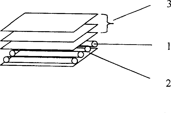
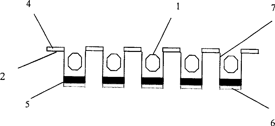
[0018] The structure of the backlight module of the present invention includes optical films such as a metal base plate, a bottom reflection film, a CCFL lamp group, a diffusion film, a prism sheet, and a protective film, and a rubber frame, and these parts are the same as those of the backlight module in the prior art. , the present invention is different from the prior art in that: as figure 2 As shown, a groove 7 is punched out on the metal base plate 2 at the position corresponding to CCFL 1. Generally, 8 U-shaped lamp tubes can be placed. The depth of the groove is about 3-5 mm larger than the radius r of CCFL. Coated on the inner surface of the metal base plate 2 (including the groove 7); CCFL 1 is respectively placed in the groove 7 of the metal base plate 2, and the plane where the axis is located is located below the reference plane where the bottom reflection film 4 is located or the inner surface of the metal base plate 2; The bottom of the groove 7 below the CCFL ...


PUM


Abstract

The invention discloses a backlight source module, including: metal base, bottom reflective film, CCFL, optical patch group, in which the metal base has a number of punching grooves corresponding to CCFL distribution location, and CCFL is placed in the punching groove. Among them, the reflective film is embedded at the bottom of CCFL in the punching groove, and the reflective film material is white rubber material with strong endothermic ability, and the surface reflection rate is considerable as the reflection rate of the bottom reflective film, and the reflective film surface close to the groove bottom is coated by the metal material with high thermal conductivity. The invention can reduce the backlight source module internal temperature, and improve the structural cooling performance; and, it can minimize the temperature difference along the lamp axis.

Description

technical field [0001] The invention relates to a backlight module of a liquid crystal display, in particular to a bottom plate (Back Cover) of the backlight module capable of reducing the internal temperature of the backlight module. Background technique [0002] Currently, the display technology of liquid crystal displays has become mature, especially in the design of backlight modules. In addition to the backlight module with CCFL (cold cathode fluorescent lamp) as the light source has become the mainstream of the market, the backlight module with LED (light-emitting diode) as the light source has gradually become the new darling of the market. However, in order to obtain higher brightness and better uniformity (especially in large-size LCD TVs), the prior art has to use a large number of CCFLs or LEDs as light sources to compensate for the large amount of light energy loss during light propagation. . [0003] Usually, the backlight module with CCFL as the light source ...

Claims


Application Information

Patent Timeline
Patent Type & Authority Patents(China)
IPC IPC(8): G02F1/1335G02F1/1333
Inventor 陈岩
Owner BEIJING BOE OPTOELECTRONCIS TECH CO LTD
Why Eureka
Try Eureka