Method for improving light intensity detector measuring accuracy

A technology of light intensity detector and measurement accuracy, which is used in microlithography exposure equipment, photolithographic process exposure devices, etc., can solve the problems of complex calibration test, rough adjustment of workpiece table, etc. The effect of improving the accuracy of position measurement

Active Publication Date: 2009-03-11
SHANGHAI MICRO ELECTRONICS EQUIP (GRP) CO LTD
View PDF4 Cites 1 Cited by
  • Summary
  • Abstract
  • Description
  • Claims
  • Application Information

AI Technical Summary

Problems solved by technology

[0006] 2 The workpiece table is roughly adjusted;
But mask pre-alignment is a complex alignment test and takes some time

Method used


Image

  • Method for improving light intensity detector measuring accuracy
  • Method for improving light intensity detector measuring accuracy
  • Method for improving light intensity detector measuring accuracy

Examples


Embodiment Construction
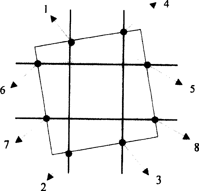
[0040] The main idea of ​​a method for improving the measurement accuracy of the light intensity detector in the present invention is to omit the pre-alignment of the test precondition mask and increase the number of sampling points for scanning 50% light intensity.

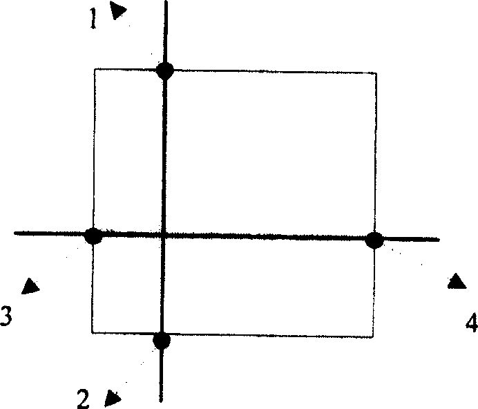
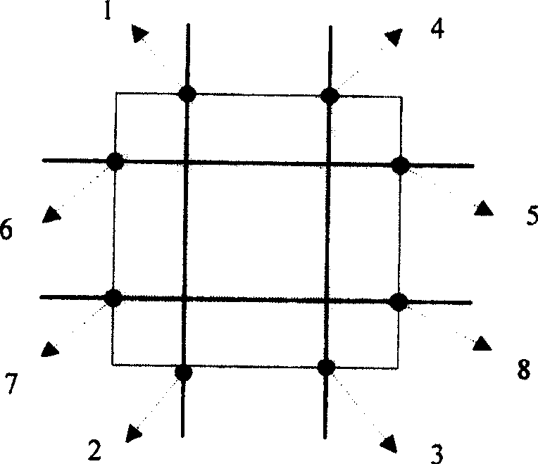
[0041] figure 2 In the test schematic diagram of the test, the light intensity detector adopts the distribution layout of eight points for the scanning sampling of the projected light area of ​​the light hole on the mask on the workpiece table, and the pre-alignment of the mask, which is the precondition of the test, is omitted. Set at least 8 light intensity sampling points for scanning in the two mutually perpendicular directions of X and Y, and the value range of light intensity is set between >0% and <100% of the reference light intensity.

[0042] The specific operation method is:

[0043] (1) Scan in the two vertical directions of X and Y respectively, and find at least 8 sampling points with 50% light in...


PUM


Abstract

Characters of the disclosed method are that omitting precondition of testing pre alignment of mask; scanning at least eight points of light intensities sampled at X, Y two perpendicular directions; numeric area of light intensity is setup between larger than 0% and less than 100%. The invention solves issue that precision of measuring position of light intensity detector is restricted by pre alignment of mask; raises precision of measured position of light intensity detector; simplifying testing procedure, and saving testing time so as to raise work efficiency.

Description

technical field [0001] The invention relates to a calibration test of photolithographic equipment, and relates to the calibration of the position of a light intensity detector on a workpiece table, in particular to a method for improving the measurement accuracy of the light intensity detector. Background technique [0002] In the calibration test of lithography equipment, there is such a test: the calibration of the position of the light intensity detector. The light intensity detector is located on the workpiece table and is used to measure the light intensity value received on the silicon wafer. In order to improve the light intensity detection accuracy of the light intensity detector, it is necessary to accurately measure the position of the light intensity detector relative to the optical axis, that is, the position relative to the center of the workpiece table. [0003] The current common practice for this test is to use a mask with square vias. The illumination ligh...

Claims


Application Information

Patent Timeline
Patent Type & Authority Patents(China)
IPC IPC(8): G03F7/20
Inventor 孙红梅
Owner SHANGHAI MICRO ELECTRONICS EQUIP (GRP) CO LTD
Why Eureka
Try Eureka