
Yarn Sensor

A sensor and yarn technology, applied in the field of yarn sensors, can solve the problems of drift of electrical components, distortion of measurement results, temperature rise of shell, etc., and achieve the effect of eliminating temperature rise, improving quality and improving wear resistance.

Inactive Publication Date: 2009-03-18
SAURER GERMANY GMBH & CO KG
View PDF9 Cites 0 Cited by
  • Summary
  • Abstract
  • Description
  • Claims
  • Application Information

AI Technical Summary

Problems solved by technology

[0007] But this type of yarn sensor proposed by the prior art cannot eliminate or avoid a series of adverse effects
Measuring devices or processors arranged inside the yarn sensor or the housing, for example, often generate heat losses that lead to a significant temperature rise in the housing
Rising temperatures can lead to unwanted and harmful so-called component drift of electrical components housed in the enclosure
Magnetic or electric fields, especially fields with fluctuating field strengths originating in the vicinity of the yarn sensor can lead to undesired distortions of the measurement results

Method used


Image

  • Yarn Sensor
  • Yarn Sensor
  • Yarn Sensor

Examples


Embodiment Construction

[0025] The application and arrangement of yarn sensors on textile machines, such as spinning machines or winding machines, are already known, for example, from the above-mentioned documents and will therefore not be described in detail here.

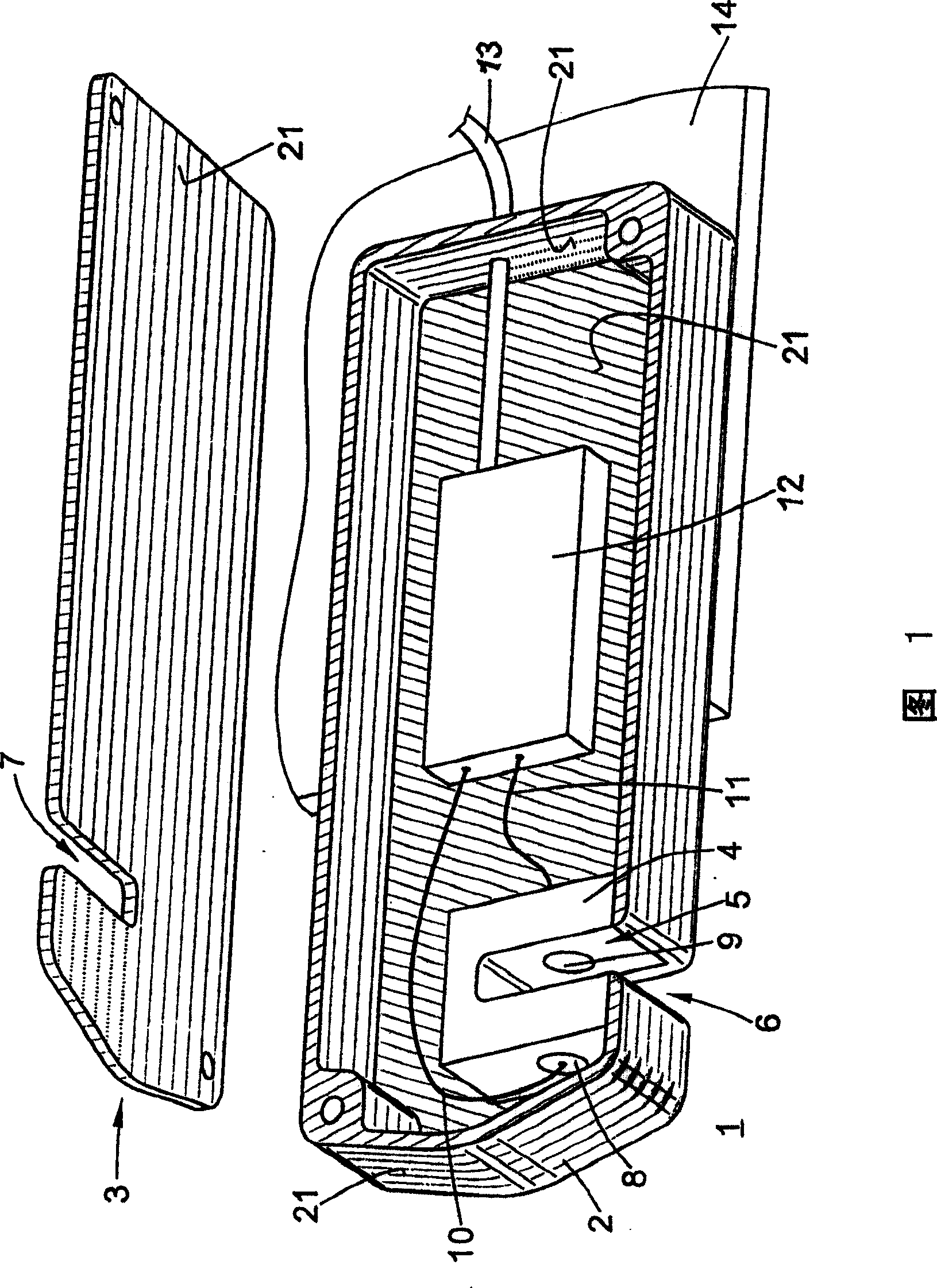
[0026] The thread sensor 1 shown in FIG. 1 has a housing comprising a box-shaped base body 2 with a removable cover 3 . The measuring device 4 is arranged in the base body 2 with a measuring gap 5 through which the yarn passes in the longitudinal direction during the measuring process. In the embodiment of FIG. 1 , the surface of the measuring gap 5 has no metal coating. The base body 2 and the cover 3 each have a recess 6 , 7 which is positioned in correspondence with the measuring gap 5 .

[0027] Measuring device 4 operates with a light sensor 9 of a light source 8 , which are each connected via lines 10 and 11 to a processor 12 . The processor 12 is attached to the bottom of the base body 2 and is designed as a so-called ASIC (Appl...


PUM

PropertyMeasurementUnit
thicknessaaaaaaaaaa
thicknessaaaaaaaaaa

Abstract

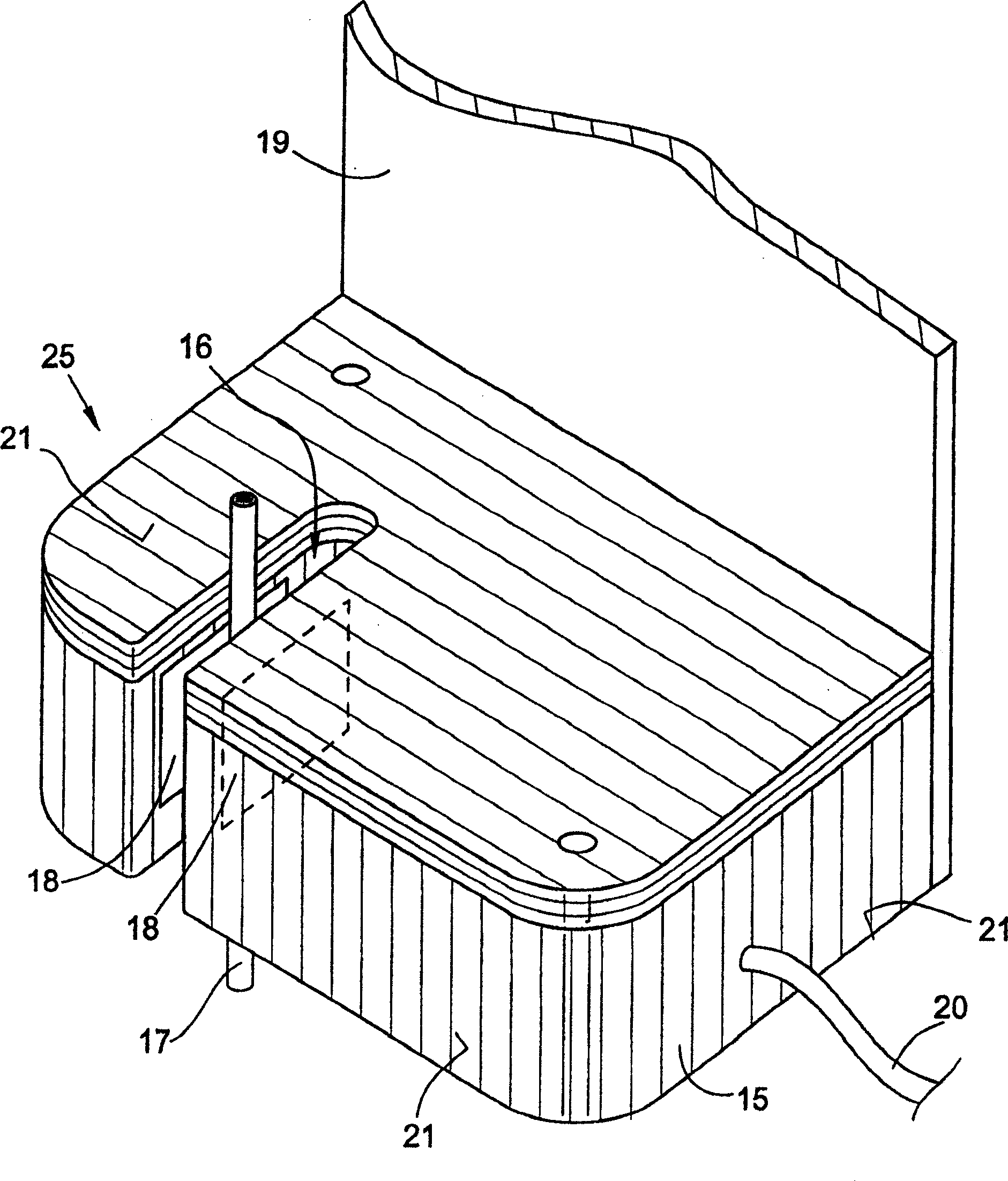
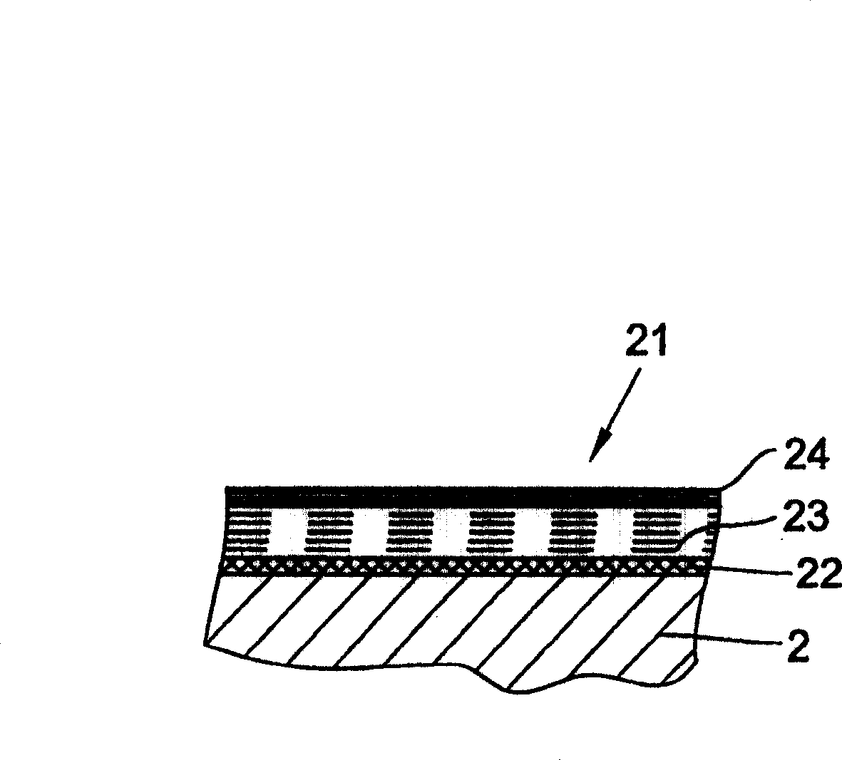
A yarn sensor for monitoring at least one parameter of a continuous yarn (17) has a measuring gap and a housing made of non-conductive plastic material and containing electronic components. The surface of the cover is covered with a metallic coating in such a way that the electronic components are surrounded by the coating (21). At least part of the surface is free of coating (21) in the measuring gap (16) of the yarn sensor (25), the metal coating of the yarn sensor (25) being connected to a thermal conductor in such a way that heat can pass Layer (21) diverges. With the yarn sensor of the present invention, adverse effects on measurement results can be significantly reduced or even completely avoided, and the quality of measurement results can be improved. The yarn sensor is especially suitable for spinning or winding machines.

Description

technical field [0001] The invention relates to a yarn sensor for monitoring at least one parameter of a continuous yarn, which has a measuring gap and a housing made of non-conductive plastic material in which various electronic components are arranged. Background technique [0002] Yarn sensors of this type are used in various configurations at various operating positions of textile machines, for example spinning machines or winding machines. Such yarn sensors are available in a metal housing in which the electronics are housed. Such mass-produced metal housings are generally produced by die-casting, since die-casting is much cheaper than machining, for example. Metals suitable for die casting are aluminum, zinc or magnesium. Although aluminum has the advantage of being light in weight, it has the disadvantage that precise contours cannot be cast from this material by die casting. Zinc can be cast into precise contours due to its low viscosity, but is more than twice as...

Claims


Application Information

Patent Timeline
Patent Type & Authority Patents(China)
IPC IPC(8): D01H13/16B65H63/02B65H63/032B65H63/06
CPCB65H63/032B65H2701/31B65H2401/13B65H2301/5305B65H2301/5133B65H63/062
Inventor O·比尔勒姆
Owner SAURER GERMANY GMBH & CO KG
Learn More