Bridge flexibility and displacement monitoring device and monitoring method
A bridge deflection and monitoring device technology, applied in measuring devices, elasticity testing, optical devices, etc., can solve the problem of long distance between laser head and receiving device, high requirements for laser beam spot position positioning, detection and monitoring effects, etc. problems, to achieve the effect of easy detection, cost reduction and monitoring conditions.
- Summary
- Abstract
- Description
- Claims
- Application Information
AI Technical Summary
Problems solved by technology
Method used
Image
Examples
Embodiment 1
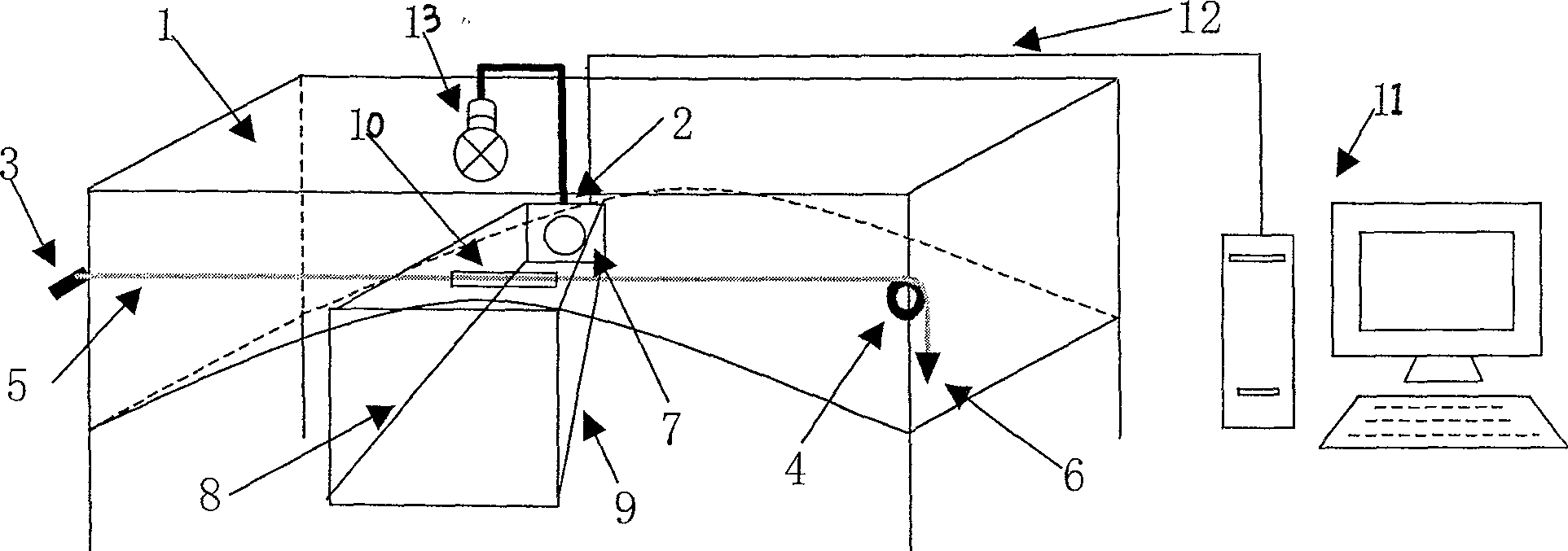
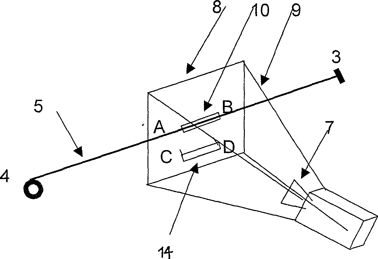
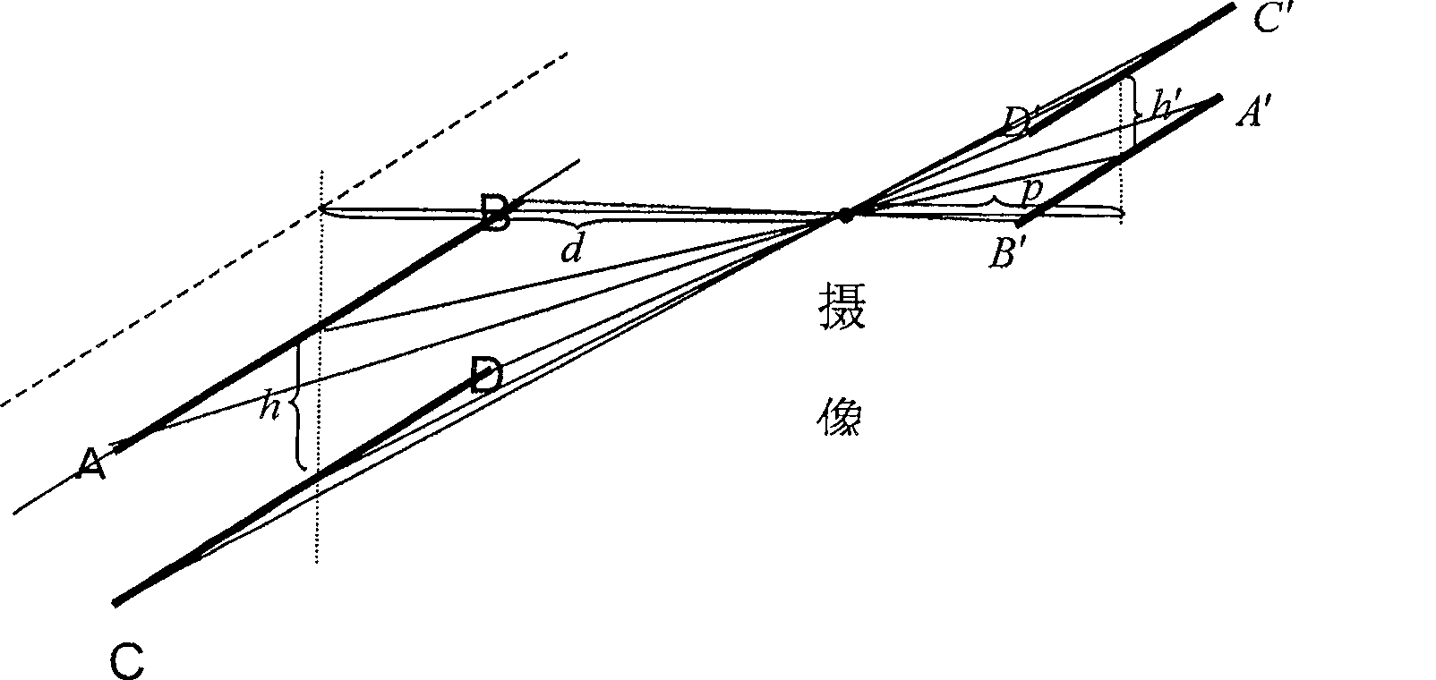
[0035] The schematic diagram of the monitoring device of the present invention is as attached figure 1 , as shown in 2. The main device is an almost horizontal stretched thin line 5 along the direction of the bridge formed by two fixed fulcrums 3 and 4 on the piers on both sides of the bridge 1 and a suspender 6 of appropriate weight. The thin line can reduce its own weight. influence, and due to the gravitational effect of the plummet 6, the thin wire can always be in a taut state; a shielding screen 8 is fixed on the point 2 to be monitored by a bracket 9, and the shielding screen 8 is facing the monitoring point 2 and is located behind the taut wire 5. position; a straight round tube is tightly sleeved on the taut line 5, and the straight round tube is just treating the monitoring point 2. The straight round pipe 10 is fixed on the tightening line 5 and will not be displaced, and its material selection requirement is a uniform straight round pipe that is not easily deforme...
Embodiment 2
[0040] The monitoring method of bridge deflection and displacement, the specific monitoring steps and methods are as follows:
[0041] 1 Equipment installation:
[0042] (1) Install a fixed fulcrum 3 and a fixed pulley 4 at appropriate positions where the pier on both sides of the bridge span 1 to be monitored is relatively stable; Pulley 4, and hang a suspender 6 of appropriate weight at the end of the line, so that the thin line 5 is always in a tight state, ensuring the stability of the reference thin line; (3) use a set of brackets on the position 2 to be monitored on the bridge span 9. Fix a shielding screen that is facing the monitoring point 2, and make the shielding screen be positioned at an appropriate position behind the tension line 5; round rod) or be called AB tightly sleeved on the taut line 5, and make AB face the monitoring point 2; The material, size, and shape of the round pipe) are the same, located directly below the straight round pipe AB, and are diffe...
PUM
 Abstract
Description
Claims
Application Information
 - R&D
- Intellectual Property
- Life Sciences
- Materials
- Tech Scout
- Unparalleled Data Quality
- Higher Quality Content
- 60% Fewer Hallucinations
Browse by: Latest US Patents, China's latest patents, Technical Efficacy Thesaurus, Application Domain, Technology Topic, Popular Technical Reports.
© 2025 PatSnap. All rights reserved.Legal|Privacy policy|Modern Slavery Act Transparency Statement|Sitemap|About US| Contact US: help@patsnap.com


