Supercharge Your Innovation With Domain-Expert AI Agents!

Small radio communication module and manufacturing method thereof

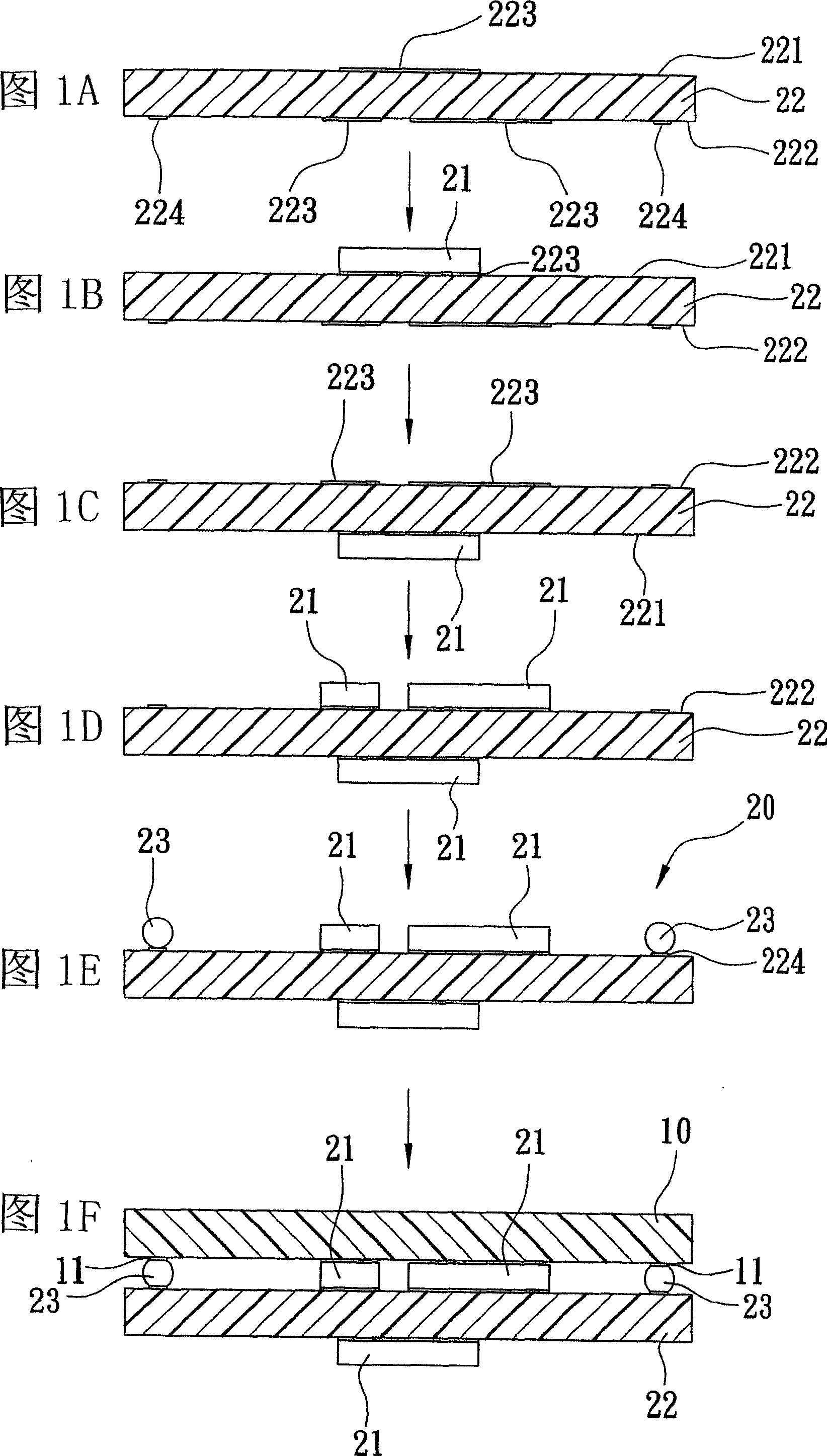
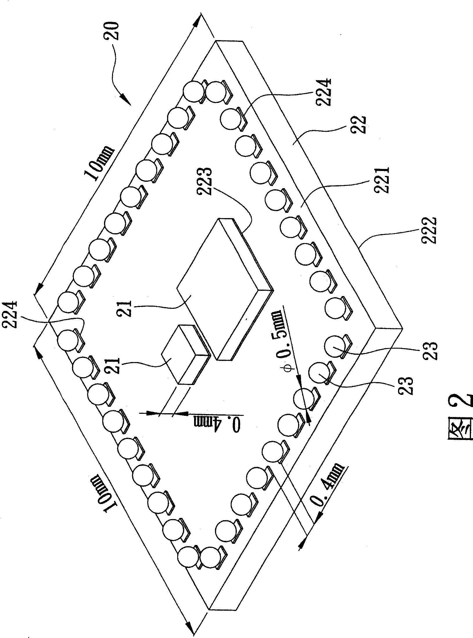
A wireless communication module and wireless communication technology, applied in the field of communication modules, can solve the problems of short circuit, enlargement, and difficulty in controlling the overall height of the solder ball 23, and achieve the effect of accurate overall height.

Active Publication Date: 2009-03-25
UNIVERSAL SCIENTIFIC INDUSTRIAL (SHANGHAI) CO LTD
View PDF4 Cites 0 Cited by
  • Summary
  • Abstract
  • Description
  • Claims
  • Application Information

AI Technical Summary

Problems solved by technology

[0014] 1. As shown in Figure 2, if the height of the chip 21 installed on the bottom surface 222 of the module substrate 22 is 0.4mm, the diameter of the solder ball 23 must be greater than 0.4mm, and in practice, solder balls of 0.5mm or more are generally used In addition, there must be a gap of at least 0.4mm between the solder balls 23, so as to avoid the occurrence of a contact short circuit between two adjacent solder balls 23. Under such conditions, if the size of the module substrate 22 It is 10×10mm, and considering that the four corners of the bottom surface 222 do not place the solder balls 23, then only 9 solder balls 23 can be accommodated on one side of the bottom surface 222, and a total of 36 solder balls can be accommodated in a circle, which is Said that the number of pins of the chip 21 cannot be greater than 36, if the complexity of the chip 21 is higher in the future, so that it cannot be used when the number of pins is greater than 36, or the size of the module substrate 22 must be increased, In this way, it will hinder the design of module miniaturization
[0015] 2. In addition, when heated, the solder ball 23 will collapse when heated, especially when there is weight to press down in the step (F), so it is not easy to control the relationship between the main board 10 and the related subsequent installation during the manufacturing process. Overall height, but also the risk of solder ball 23 short circuit
[0016] 3. Although it can be completed with only one substrate, the price of the ball planting machine and other related equipment is quite expensive. General manufacturing plants do not have ball planting equipment and technology. If the general manufacturing plant has passed the inspection, the wireless communication module needs to be disassembled 20, the removed wireless communication module 20 needs to be sent back to the packaging factory for re-balling, so that it can be used again, so it will be quite time-consuming and labor-intensive

Method used


Image

  • Small radio communication module and manufacturing method thereof
  • Small radio communication module and manufacturing method thereof
  • Small radio communication module and manufacturing method thereof

Examples


Embodiment Construction

[0033] Before the present invention is described in detail, it should be noted that in the following description, similar elements are denoted by the same numerals.

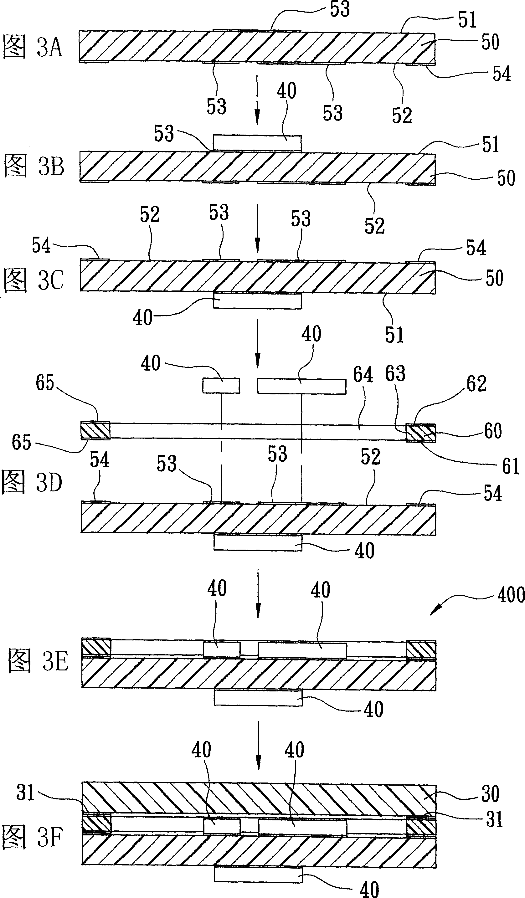
[0034] As shown in Figures 3A-3F and 4, the first preferred embodiment of the miniaturized wireless communication module of the present invention is used to be arranged in a device with a wireless communication function, and the device includes a host with a plurality of welding pads 31 board 30 , the miniaturized wireless communication module 400 includes three chips 40 , a module substrate 50 , and a carrier substrate 60 .

[0035] One of the chips 40 is a chip for a communication circuit.

[0036] The module substrate 50 includes a top surface 51, a bottom surface 52, a plurality of first welding pads 53 arranged on the top surface 51 and the bottom surface 52, and a plurality of second welding pads 54 arranged on the bottom surface 52. The pad 53 is located in the middle, the second pad 54 is located on the ...


PUM


Abstract

A miniaturized radio communication module consists of two chips, a module base plate with the first welding pad and the second welding pad at bottom surface and top surface, and a bearing module. Its preparing method includes setting said chips on the first welding pad at bottom and top surfaces of module base plate separately and setting said bearing base plate on bottom surface of module base plate.

Description

【Technical field】 [0001] The invention relates to a communication module, in particular to a miniaturized wireless communication module and a manufacturing method thereof. 【Background technique】 [0002] As shown in Figures 1 and 2, the conventional wireless communication module is used to be set in a device with wireless communication function, the device includes a motherboard 10 with a plurality of welding pads 11, and the wireless communication module 20 includes three Chip 21 , a module substrate 22 , and a plurality of solder balls 23 . [0003] One of the chips 21 is a chip for a communication circuit. [0004] The module substrate 22 includes a top surface 221, a bottom surface 222, a plurality of first welding pads 223 arranged on the top surface 221 and the bottom surface 222, and a plurality of second welding pads 224 arranged on the bottom surface 222. The chip 21 is the first pad 223 provided on the top and bottom 221 and 222 respectively. [0005] The solder...

Claims


Application Information

Patent Timeline
Patent Type & Authority Patents(China)
IPC IPC(8): H01L25/00H01L23/00H01L21/50H05K13/00H04B7/00
Inventor 廖国宪陈嘉扬王垂堂
Owner UNIVERSAL SCIENTIFIC INDUSTRIAL (SHANGHAI) CO LTD
Features
  • R&D
  • Intellectual Property
  • Life Sciences
  • Materials
  • Tech Scout
  • Unparalleled Data Quality
  • Higher Quality Content
  • 60% Fewer Hallucinations
Learn More