Gear type machining tip and tool attaching the same thereon

一种加工工件、顶端的技术,应用在石材加工工具、锯床装置的刀具、制造工具等方向,能够解决柄部弯曲、切削工具损坏、施加过大加工负载等问题

Inactive Publication Date: 2009-05-13
NIWA DAIYAMONDO INDS
View PDF9 Cites 1 Cited by
  • Summary
  • Abstract
  • Description
  • Claims
  • Application Information

AI Technical Summary

Problems solved by technology

In the case where the cutting tool is applied to a machine for continuous use under fixed machining conditions (e.g., feed rate, depth of cut, and rotational speed), the cutting load suddenly increases, thereby applying excessive force to both the tool and the machine. processing load
As a result, the shank may be bent, the cutting tool may not be able to machine the workpiece into the desired shape, or the cutting tool may be damaged

Method used


Image

  • Gear type machining tip and tool attaching the same thereon
  • Gear type machining tip and tool attaching the same thereon
  • Gear type machining tip and tool attaching the same thereon

Examples


Embodiment Construction

[0070] The preferred embodiments of the present invention will now be described in detail, and the embodiments thereof are shown in these drawings.

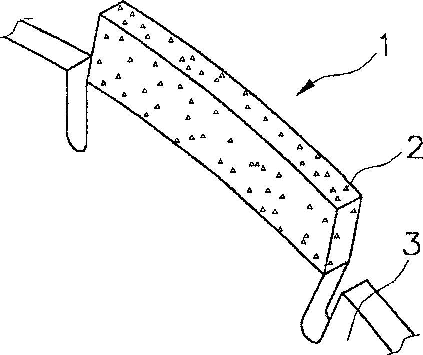
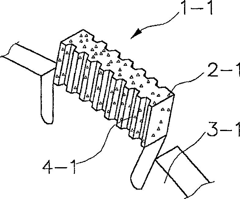
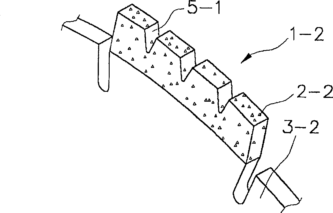
[0071] The zigzag cutting tip of the present invention with a double-layer structure includes: an adhesive layer containing super wear-resistant particles therein and having grooves formed on the working surface in contact with the workpiece; and a spacer layer To install the adhesive layer on the handle. The serrated cutting tip of the present invention is divided into a segmented cutting tip and a continuous rim type cutting tip. In addition, the cutting tip of the present invention is installed on the outer periphery of the cutting tool of the present invention, and the cutting tool is classified into cutting tools, grinding tools, and drilling tools according to functions. The preferred embodiment of the present invention will be described below with reference to the segmented cutting tip, but this is only for illustration.

[00...


PUM


Abstract

The invention relates to a serrated cutting tip and a serrated cutting tool having the cutting attached thereto capable of working a work piece at a fixed workability. The cutting tip includes a bond layer, which has super abrasive particles contained therein and grooves formed on a face which is in contact with the work piece, and a blank layer for strongly supporting the bond layer, by which a working plane of the cutting tip contacting the work piece is uniformly maintained during working use and debris can be readily discharged. As a result, workability is improved and lifetime is prolonged.

Description

Technical field [0001] The present invention relates to a cutting tool for cutting, grinding or drilling a workpiece (for example, concrete or stone), and more specifically to a sawtooth-shaped cutting tip with a double-layer structure capable of processing a workpiece at a predetermined processing speed , And a serrated cutting tool with the cutting tip mounted on it. Background technique [0002] First, provide a general definition for the terms in the specification, and these terms will be used consistently throughout the specification. [0003] Super wear-resistant materials or super wear-resistant particles refer to super-hard particles usually formed of diamond or cubic boron nitride (CBN) with relatively high hardness. [0004] The cutting tip refers to the main body used to grind or cut a workpiece. It is made by a manufacturing process that includes the steps of mixing super wear-resistant particles with a binder, and is divided into a segmented tip and a continuous rim ...

Claims


Application Information

Patent Timeline
Patent Type & Authority Patents(China)
IPC IPC(8): B28D1/12B23D61/02B23D61/04B24D5/12B24D99/00B28D1/04
CPCB28D1/041B24D5/123B24D99/005B28D1/121B23D61/023B28D1/12
Inventor 金秀光李昌弦崔仁硕
Owner NIWA DAIYAMONDO INDS
Why Eureka
Try Eureka