Diamagnetic suspension rotor electrostatic driving micro-gyroscope

A magnetic levitation rotor, electrostatic drive technology, applied in the direction of rotating gyroscope, gyroscope/steering sensing equipment, using gyroscope for acceleration measurement, etc., can solve the problems of complex process and achieve the effect of simple process

Inactive Publication Date: 2009-05-13
SHANGHAI JIAOTONG UNIV
View PDF5 Cites 0 Cited by
  • Summary
  • Abstract
  • Description
  • Claims
  • Application Information

AI Technical Summary

Problems solved by technology

Its shortcoming is that it is necessary to provide a floating electrostatic force electrode and a control electrode that stabilizes the position of the X and Y axes, and the process is relatively complicated

Method used


Image

  • Diamagnetic suspension rotor electrostatic driving micro-gyroscope
  • Diamagnetic suspension rotor electrostatic driving micro-gyroscope
  • Diamagnetic suspension rotor electrostatic driving micro-gyroscope

Examples


Embodiment Construction

[0019] An embodiment of the present invention will be described in detail below in conjunction with the accompanying drawings: this embodiment is implemented on the premise of the technical solution of the present invention, and detailed implementation methods and specific operating procedures are provided, but the protection scope of the present invention is not limited to Examples described below.

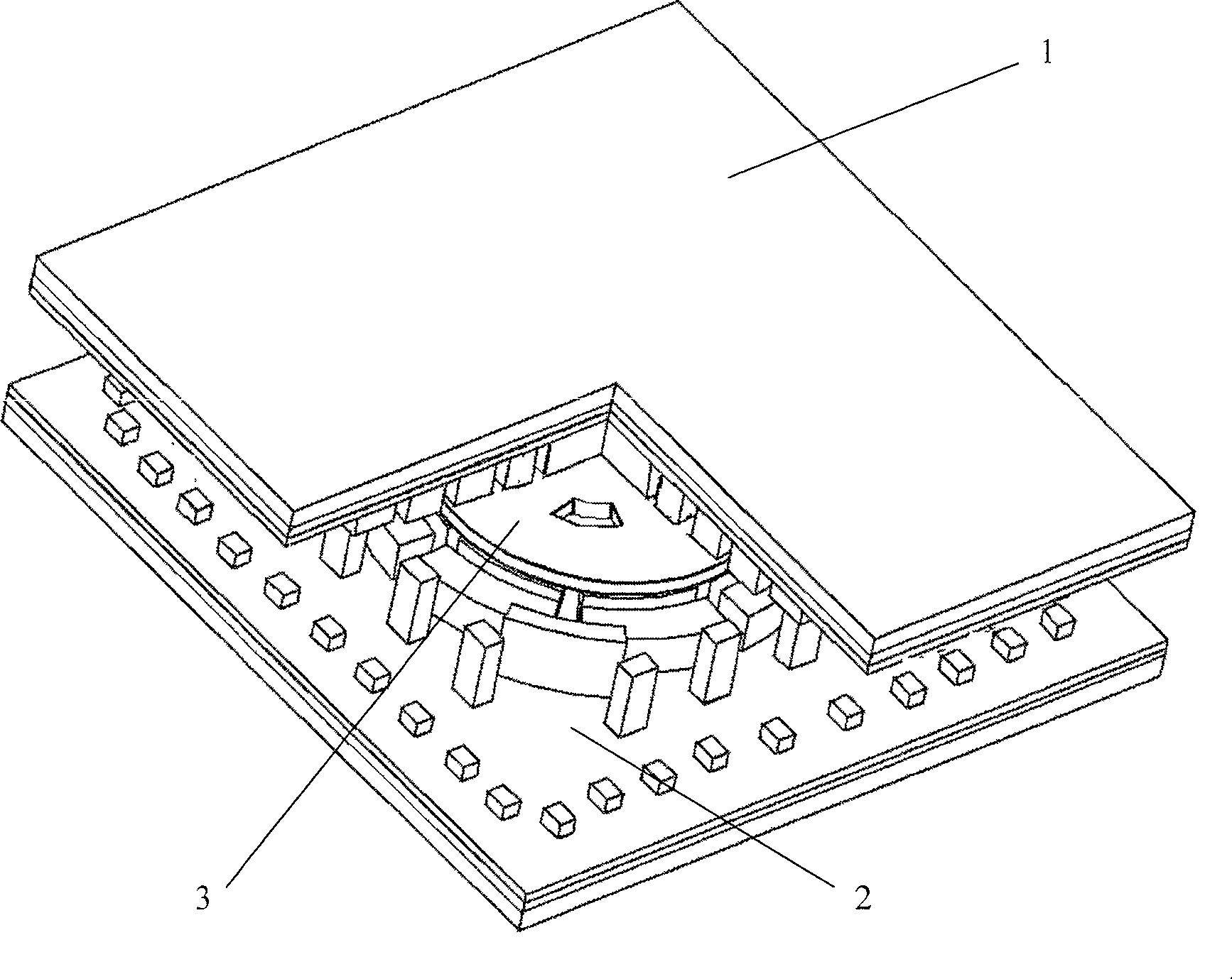
[0020] Such as figure 1 , what the present invention adopts is three-layer structure, is made of upper stator 1, rotor 3 and lower stator 2. The upper stator 1 and the lower stator 2 are electrically and mechanically connected by bonding, and form a cavity, and the rotor 3 is placed in the cavity.

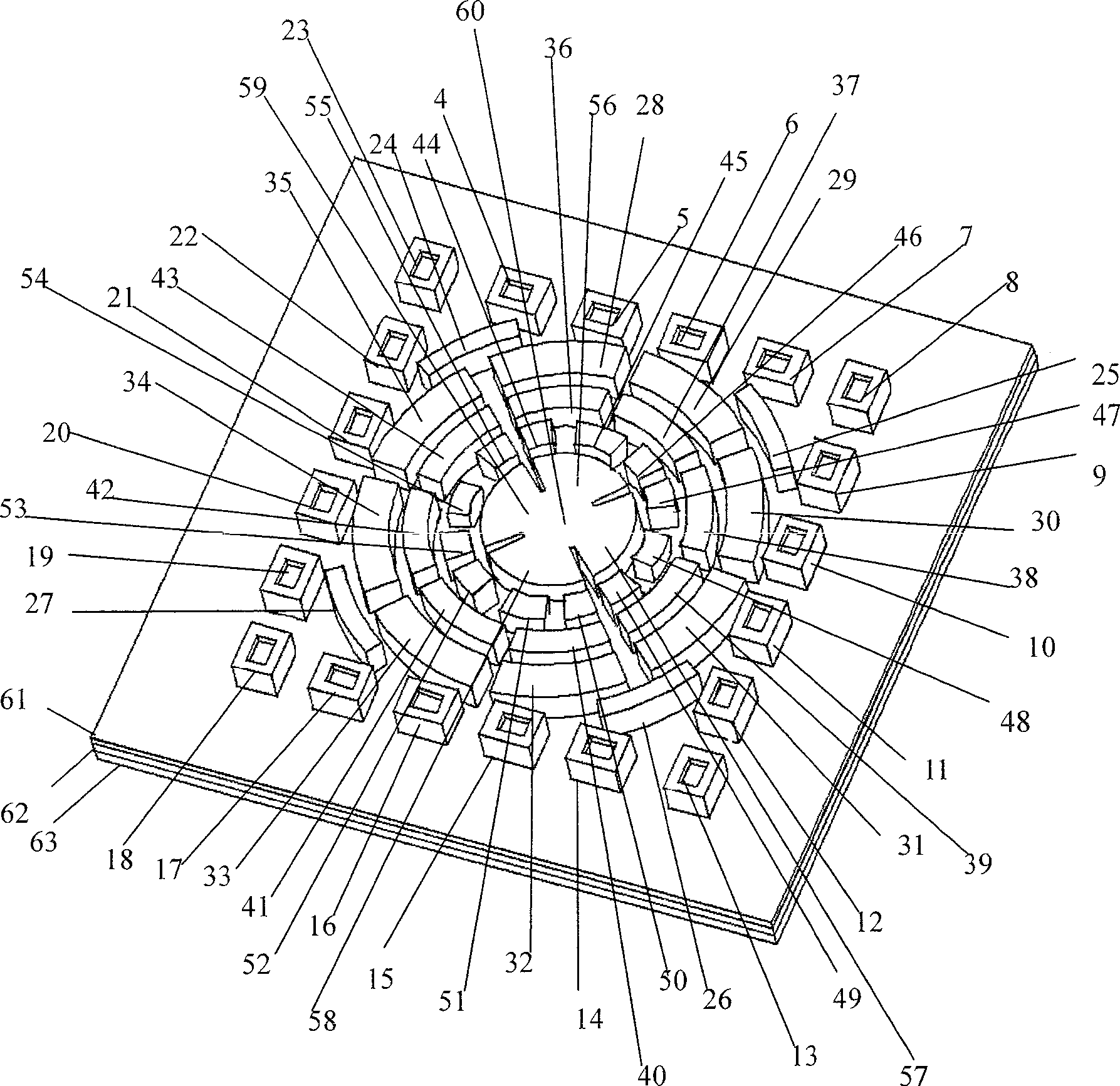
[0021] Such as figure 2, the upper stator 1 includes: the first upper right electrical conduction groove 4, the second upper right electrical conduction groove 5, the third upper right electrical conduction groove 6, the fourth upper right electrical conduction groove 7, The first...


PUM


Abstract

A reverse magnetic suspension rotor electrostatic driving micro gyro belongs to micro-electromechanical technology field. The invention is composed of an upper stator, a rotor and a lower stator. It takes upper and lower stators rotating capacity polar plates to drive variable-capacitance electrostatic rotating. Charging magnetism to four sectors of public capacity polar plate construction composed of upper and lower stators which are made of permanent-magnet materials and capacity polar plates of upper and lower stators to detect z axle linear acceleration and wind x, y axles angular acceleration. Utilize diamagnetic materials to make rotor chip. Provide a reverse magnetic suspension rotor electrostatic driving micro gyro adopting combination of permanent-magnet and diamagnetic materials to realize self-stabilization suspension, which leaves out static suspension controlling units providing suspension electrostatic coils or capacity polar plates etc. It can detects x, y, z axles linear acceleration and x, y axles angular acceleration simultaneously, which can realize precision positioning of objects, detect linear and angular acceleration or navigate.

Description

technical field [0001] The invention relates to a miniature gyroscope in the field of micro-electromechanical technology, in particular to a miniature gyroscope driven by an anti-magnetic levitation rotor electrostatically. Background technique [0002] With the development of MEMS technology, inertial sensing devices have become one of the most successful and widely used MEMS devices in the past few years. Mainly driven by the automotive industry, micromachined vibratory mechanical gyroscopes have been extensively studied over the past few years, with significantly improved performance. At the same time, in order to overcome the suspension symmetry structure of vibrating micro-mechanical gyroscopes and the sensitivity of mode matching to manufacturing defects, temperature changes, etc., it is possible to improve the structural design of vibrating micro-gyroscopes, and on the other hand, try to develop new types of gyroscopes. The micro-gyroscope with structural method and ...

Claims


Application Information

Patent Timeline
Patent Type & Authority Patents(China)
IPC IPC(8): G01C19/00G01P15/14G01C19/02G01C19/24G01P15/18
Inventor 张卫平张忠榕陈文元刘武
Owner SHANGHAI JIAOTONG UNIV
Why Eureka
Try Eureka