
Reflect type microlens optical engine illumination system

A lighting system and light engine technology, applied in optics, optical components, instruments, etc., can solve the problems of large loss of light energy and difficult assembly, and achieve the effect of reducing the difficulty of the process and improving the utilization rate of light energy.

Inactive Publication Date: 2009-05-13
SHENZHEN ACTO DIGITAL VIDEO TECH
View PDF7 Cites 0 Cited by
  • Summary
  • Abstract
  • Description
  • Claims
  • Application Information

AI Technical Summary

Problems solved by technology

It is difficult to assemble with oblique lighting, the lighting spot is trapezoidal or diamond-shaped, and the loss of light energy is relatively large

Method used


Image

  • Reflect type microlens optical engine illumination system
  • Reflect type microlens optical engine illumination system
  • Reflect type microlens optical engine illumination system

Examples


Embodiment Construction

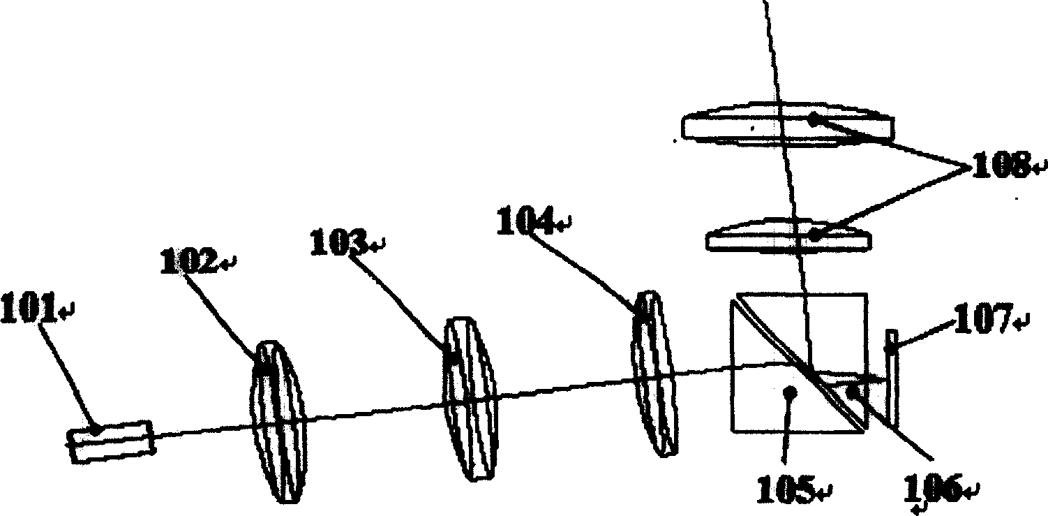
[0009] figure 1 It is the light path diagram of the illumination light path of the existing reflective micromirror light engine. The light emitted by the light pipe 101 is incident on the refracting prism 105 through the illuminating lenses 102 , 103 , 104 . The incident angle of light on the slope of the refracting prism 105 is smaller than the critical angle of total reflection. The light emitted from the oblique surface of the refracting prism 105 is incident on the reflective micromirror 107 through the reflective prism 106 . Since the exit faces of 107 and 101 are non-conjugated, the light spot formed on 107 is rhombus or trapezoid. The light is incident on the slope of the reflective prism 106 after being reflected by the reflective micromirror 107 . The incident angle of the light on the slope of the reflective prism 106 is greater than the critical angle of total reflection. The light reflected by the slope 106 is imaged onto the screen by the projection lens 108 ....


PUM


Abstract

The invention relates to the DLP optical engine projection display. Existing DLP optical engine mainly uses oblique lighting. Through oblique lighting assembly is relatively difficult, with the lighting light being ladder or diamond shape to have bigger optical energy loss. It displaces the light pipe relative to the lighting lens along the light shaft, with emitted light going through the diamond mirror to be incident on the micro display, the light mark of the lighting being square to improve the light utilization rate. It uses reverse TIR diamond, with space between two diamonds having no affect to the projection lens imaging, with reduced processing difficulty.

Description

【Technical field】 [0001] The invention belongs to the field of projection display of reflective micro-mirror light engine, in particular to the field of projection display of DLP optical engine. 【Background technique】 [0002] DLP optical engine is mainly composed of light source, light pipe, color wheel, lighting system, DMD chip and projection lens. The light emitted from the light source is split by the color wheel in time sequence, and a uniform light spot is formed by the light pipe, and is imaged by the lighting system onto the DMD chip. Compose a color image. At present, the lighting method of DLP optical engine is mainly oblique lighting. It is difficult to assemble with oblique lighting, the lighting spot is trapezoidal or rhombus, and the loss of light energy is relatively large. 【Content of invention】 [0003] The technical problem to be solved by the present invention is to overcome the phenomenon that the prior art DLP optical engine adopts the oblique ligh...

Claims


Application Information

Patent Timeline
Patent Type & Authority Patents(China)
IPC IPC(8): G03B21/14G02B27/18
Inventor 樊思民
Owner SHENZHEN ACTO DIGITAL VIDEO TECH
Learn More