Reactor
A reaction device and reaction technology, applied in the direction of fuel cells, inorganic chemistry, electrochemical generators, etc., can solve the problems of reduced rigidity, complicated assembly, reactor deformation, etc., and achieve the effects of difficult deformation, easy assembly, and improved rigidity
- Summary
- Abstract
- Description
- Claims
- Application Information
AI Technical Summary
Problems solved by technology
Method used
Image

Examples
no. 1 Embodiment approach
[0109] First, the first embodiment of the reaction apparatus of the present invention will be described.
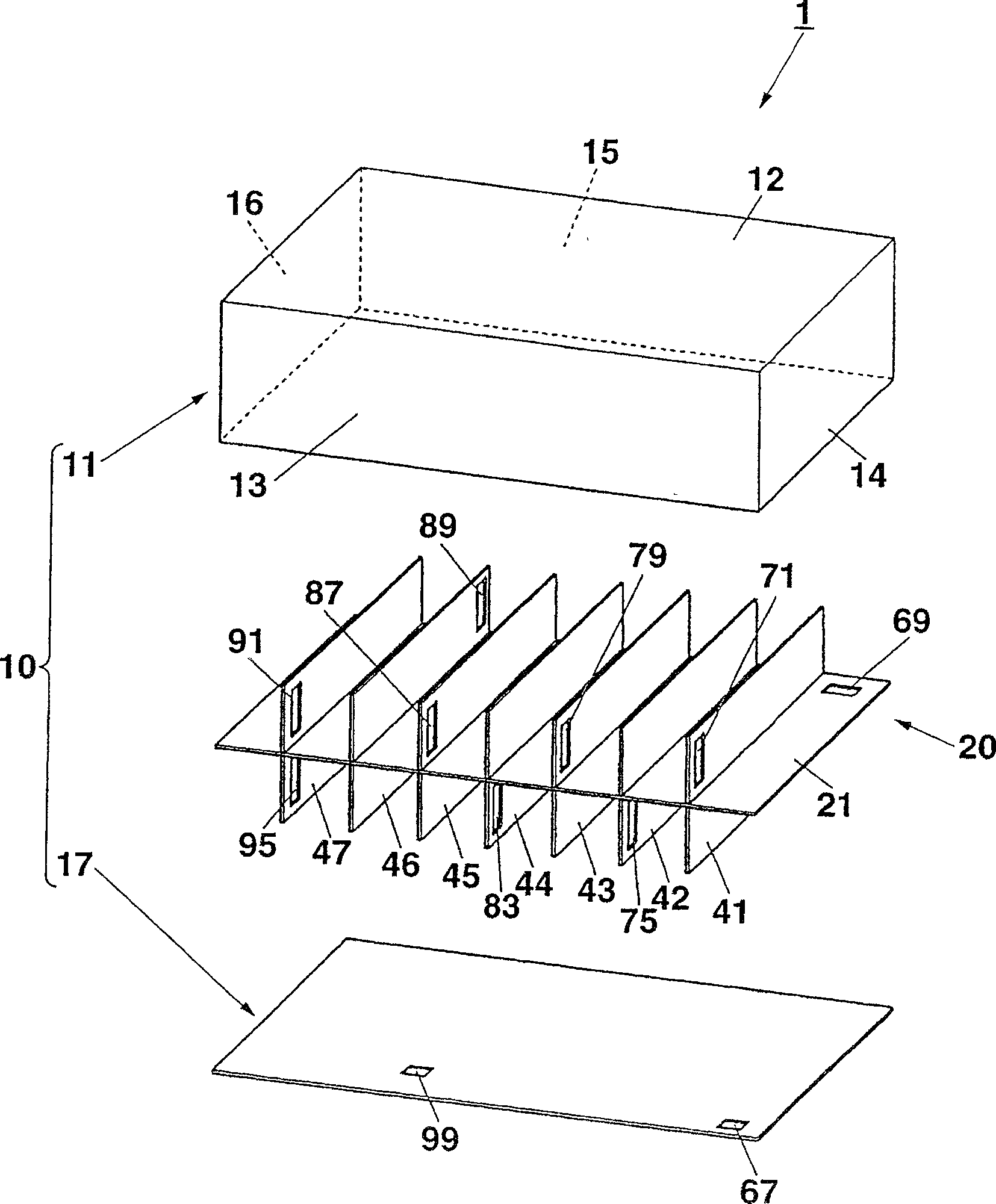
[0110] figure 1 It is an exploded perspective view of the reactor of the first embodiment of the reaction apparatus of the present invention viewed obliquely from above.
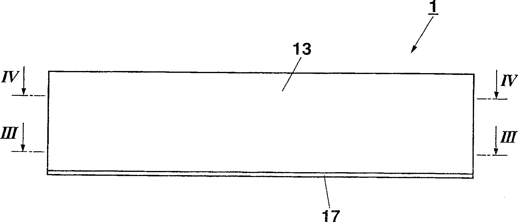
[0111] Figure 2A , 2B It is a top view and a side view of the reactor of this embodiment.
[0112] Figure 3 is Figure 2B Sectional view of III-III direction.
[0113] Figure 4 is Figure 2B The IV-IV cross-sectional view.
[0114] Such as figure 1 As shown, the reactor 1 includes a reaction vessel 10 and a partition member 20 accommodated in the reaction vessel 10 .
[0115] The reaction vessel 10 includes a box-shaped member 11 and a bottom plate 17 . The box-shaped member 11 has: a rectangular top plate 12; a pair of side plates 13, 15, which are arranged on opposite sides of the four sides of the top plate 12, and are connected in a state of being vertically connected to the top plate 12; ...
no. 2 Embodiment approach
[0152] Next, a second embodiment of the reaction container of the present invention will be described.
[0153] Fig. 9 is a side view of the microreactor module of the second embodiment of the reaction apparatus of the present invention.
[0154] Fig. 10 is a schematic side view when dividing the microreactor module of this embodiment by function.
[0155] For example, the microreactor module 600 is a reaction device built in electronic devices such as notebook personal computers, PDAs, electronic notebooks, digital cameras, mobile phones, watches, recorders, and projectors to generate hydrogen used in fuel cells.
[0156] As shown in Figures 9 and 10, the microreactor assembly 600 has: a supply and discharge part 602 for supplying reactants and discharging products; a high temperature reaction part 604 (the first reaction part) is set at a relatively high The temperature of the low-temperature reaction part 606 (second reaction part) is set at a temperature lower than the se...
no. 3 Embodiment approach
[0241] Next, a third embodiment of the reaction apparatus of the present invention will be described.
[0242] Figure 20 It is an exploded perspective view of the reactor of the third embodiment of the reaction apparatus of the present invention viewed obliquely from below.
[0243] Figure 21A , 21B It is a plan view and a bottom view of the reactor of this embodiment.
[0244] Figure 22 yes Figure 21B Sectional view of III-III direction.
[0245] Figure 23 yes Figure 21A The IV-IV cross-sectional view.
[0246] As shown in the figure, this reactor 400 includes: a box-shaped member 410 with an opening on the lower bottom surface; The bottom plate 430.
[0247] The box-shaped member 410, the partition plate 420, and the bottom plate 430 may be made of plate-shaped metal material such as stainless steel, ceramic material, glass material, or resin material.
[0248] The box-shaped member 410 has: a top plate 412 formed into a square or a rectangle; a pair of side...
PUM
 Abstract
Description
Claims
Application Information
 - R&D
- Intellectual Property
- Life Sciences
- Materials
- Tech Scout
- Unparalleled Data Quality
- Higher Quality Content
- 60% Fewer Hallucinations
Browse by: Latest US Patents, China's latest patents, Technical Efficacy Thesaurus, Application Domain, Technology Topic, Popular Technical Reports.
© 2025 PatSnap. All rights reserved.Legal|Privacy policy|Modern Slavery Act Transparency Statement|Sitemap|About US| Contact US: help@patsnap.com