
Substrate transfer device and cleaning method thereof and substrate processing system and cleaning method thereof

A substrate processing system and substrate conveying technology, which is applied in the field of substrate processing system and its cleaning, can solve the problems of difficulty in removing particles, lower operating rate of substrate processing system, and inability to transport wafers immediately, and achieve the effect of preventing electrification

Inactive Publication Date: 2009-07-29
TOKYO ELECTRON LTD
View PDF8 Cites 0 Cited by
  • Summary
  • Abstract
  • Description
  • Claims
  • Application Information

AI Technical Summary

Problems solved by technology

[0007] When the operator cleans the inside of the substrate transfer chamber 64 with scrubbing components, etc., since the maintenance window (not shown) communicates with the external environment (maintenance area), like this, the dust in the atmosphere will invade into the substrate transfer chamber 64 as particles, Make it difficult to completely remove the particles accumulated in the substrate transport chamber 64
In addition, after the operator cleans and returns to the normal state, the substrate transfer chamber 64 needs to be evacuated and dried, and the wafer cannot be transferred immediately. In this way, the actual operation rate of the substrate processing system will also decrease.

Method used


Image

  • Substrate transfer device and cleaning method thereof and substrate processing system and cleaning method thereof
  • Substrate transfer device and cleaning method thereof and substrate processing system and cleaning method thereof
  • Substrate transfer device and cleaning method thereof and substrate processing system and cleaning method thereof

Examples


Embodiment

[0087] Embodiments of the present invention will be specifically described below.

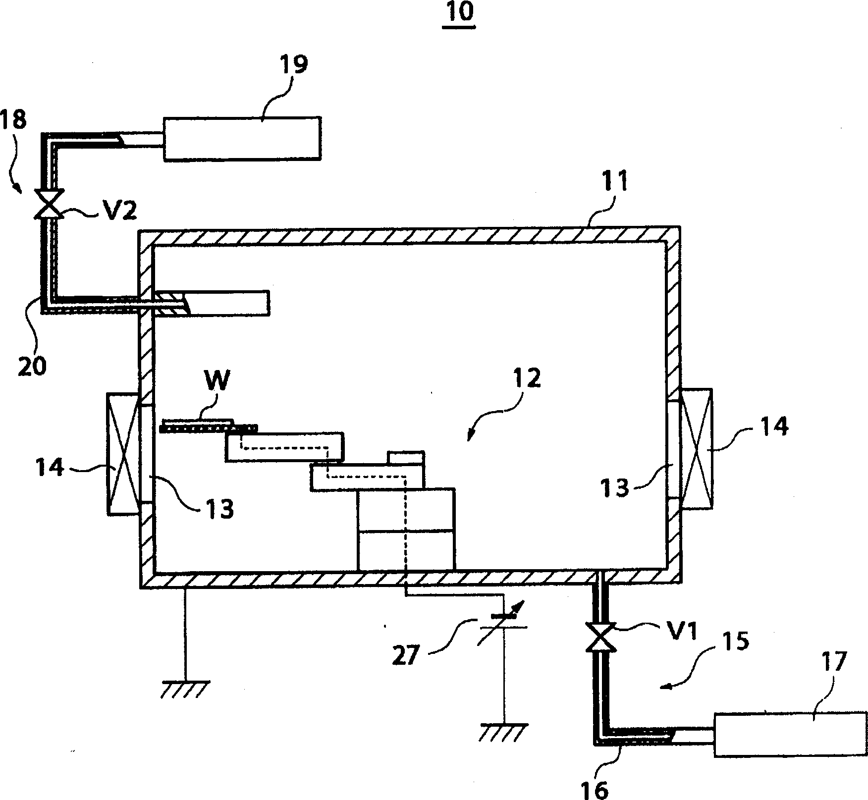
[0088] The following embodiments have been implemented in the substrate transfer apparatus 10 described above.

[0089] Figure 4 It is a flow chart showing the evaluation procedure of particle removal processing implemented as an embodiment of the present invention.

[0090] First, the wafer W is carried into the chamber 11 of the substrate transfer device 10, and the initial PWP (Particle per Wafer Pass) is measured by counting the number of particles adhering to the transferred wafer W (step S41). Next, the maintenance window of the substrate transfer device 10 is opened to allow dust in the atmosphere to enter the chamber 11 (step S42). Then, the maintenance window of the substrate transfer device 10 is closed, and the counter of the control device (not shown) of the substrate transfer device 10 is set to "1".

[0091] (Step S43), implement the cleaning method of the above-mentioned subs...


PUM


Abstract

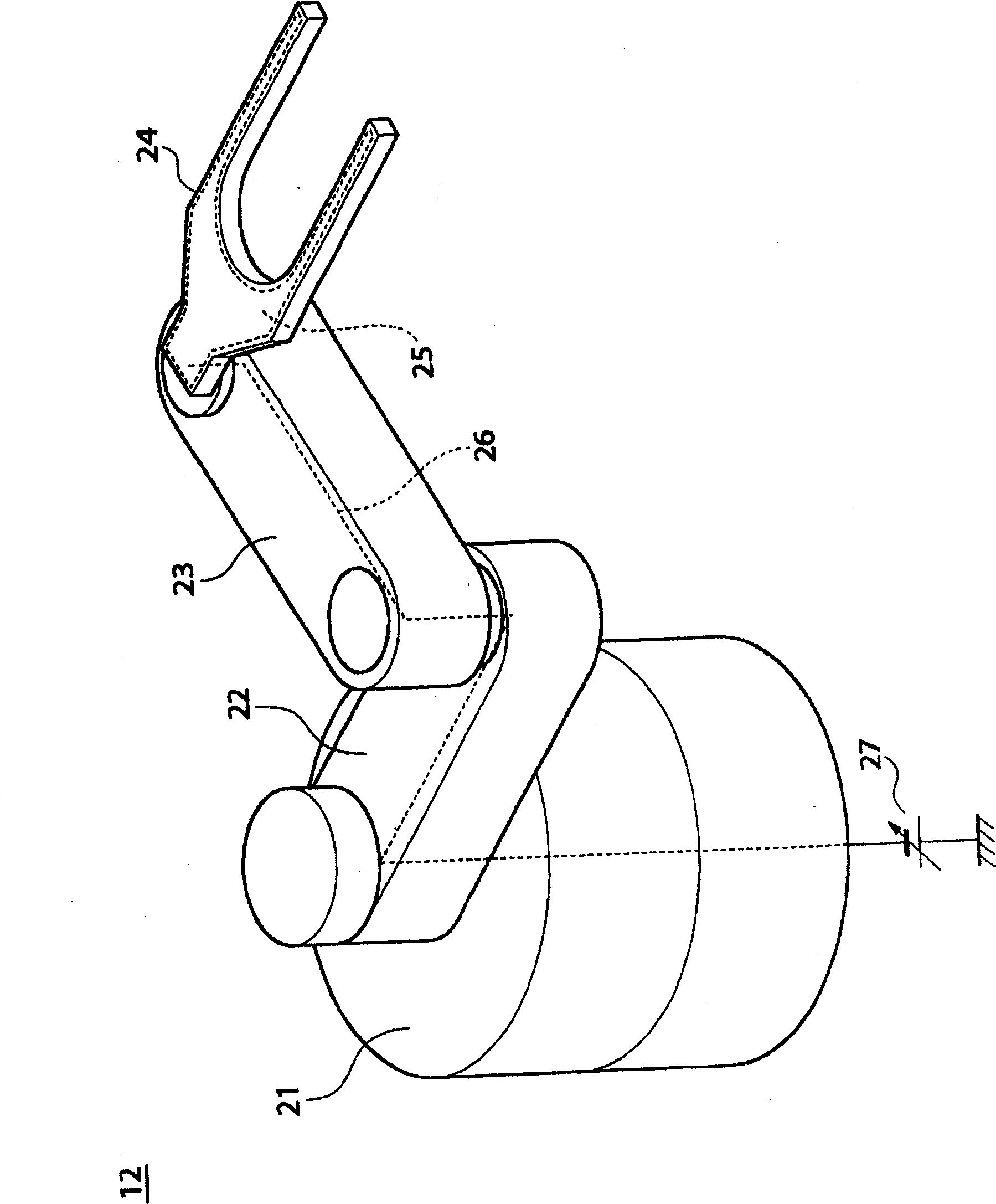
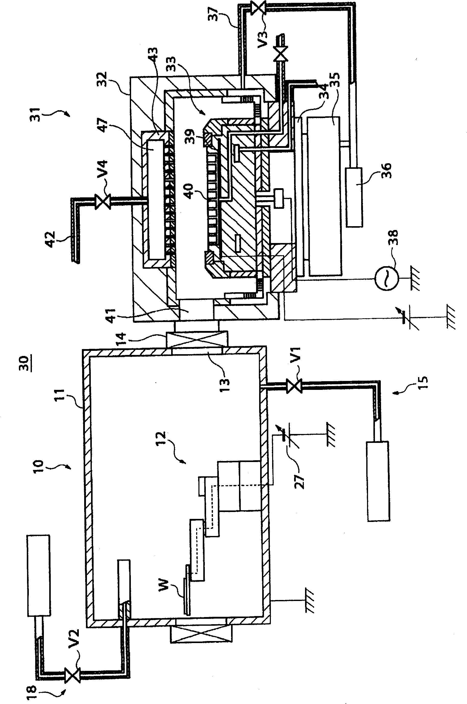
PROBLEM TO BE SOLVED: To provide a substrate transport device which can sufficiently remove deposited particles without deteriorating an operation ratio of a substrate processing system. SOLUTION: The substrate transport device 10 is provided with a chamber 11 in a box shape, a transport arm 12 disposed in the chamber 11, an exhaust line 15 exhausting inside of the chamber 11 and a gas introduction line 18 introducing N<SB>2< / SB>gas into the chamber 11. The transport arm 12 moves a pick having an electrode layer to which high voltage is applied to the desired position of the chamber 11. N<SB>2< / SB>gas is introduced into the chamber 11 by the gas introduction line 18, inside of the chamber 11 is exhausted by the exhaust line 15 and a viscous flow is generated in the chamber 11. High voltage is applied to the electrode layer of the pick moved to the desired position. Thus, an electrostatic field is generated between the inner face of the chamber 11 and the pick, and electrostatic stress is operated on the inner face of the chamber 11 where the particles are deposited. COPYRIGHT: (C)2006,JPO&NCIPI

Description

technical field [0001] The present invention relates to a substrate conveying device and a cleaning method thereof, a substrate processing system and a cleaning method thereof, and in particular, to a substrate conveying device for cleaning the inside of the substrate conveying device in a state not open to the atmosphere, a cleaning method thereof, a substrate processing system and its cleaning method. Background technique [0002] As we all know, at present, as a substrate processing system that performs various plasma treatments such as ion doping, film formation, and etching on a substrate, it is known that a plurality of substrate processing devices are arranged radially to bundle substrates through a common substrate transfer chamber. processing system. [0003] Such cluster substrate processing systems such as Image 6 As shown in (a), it includes: for example, two substrate processing devices 61 for processing wafers; a loading assembly 62 for loading and unloading ...

Claims


Application Information

Patent Timeline
IPC IPC(8): B65G49/05B65G49/07H01L21/00H01L21/68H01L21/677H01L21/02H01L21/304
CPCB25J11/0095H01J37/32862H01L21/67069
Inventor 守屋刚中山博之
Owner TOKYO ELECTRON LTD
Learn More