
Bridge circuit type current limiting energy storage circuit

An energy storage circuit and current limiting technology, applied in the field of bridge type current limiting energy storage circuit, can solve the problems of inability to meet instantaneous high power exchange, slow charging and discharging speed of battery energy storage, and small energy storage capacity of super capacitors.

Inactive Publication Date: 2009-08-12
INST OF ELECTRICAL ENG CHINESE ACAD OF SCI
View PDF3 Cites 6 Cited by
  • Summary
  • Abstract
  • Description
  • Claims
  • Application Information

AI Technical Summary

Problems solved by technology

The charging and discharging speed of battery energy storage is slow, cannot meet the instantaneous high power exchange, and has environmental pollution problems; the energy storage capacity of supercapacitor is small, and the number of charge and discharge times is limited; pumped energy storage is limited by the environment, and the efficiency is too low

Method used


Image

  • Bridge circuit type current limiting energy storage circuit
  • Bridge circuit type current limiting energy storage circuit

Examples


Embodiment Construction

[0012] The present invention will be further described below in conjunction with the drawings and embodiments:

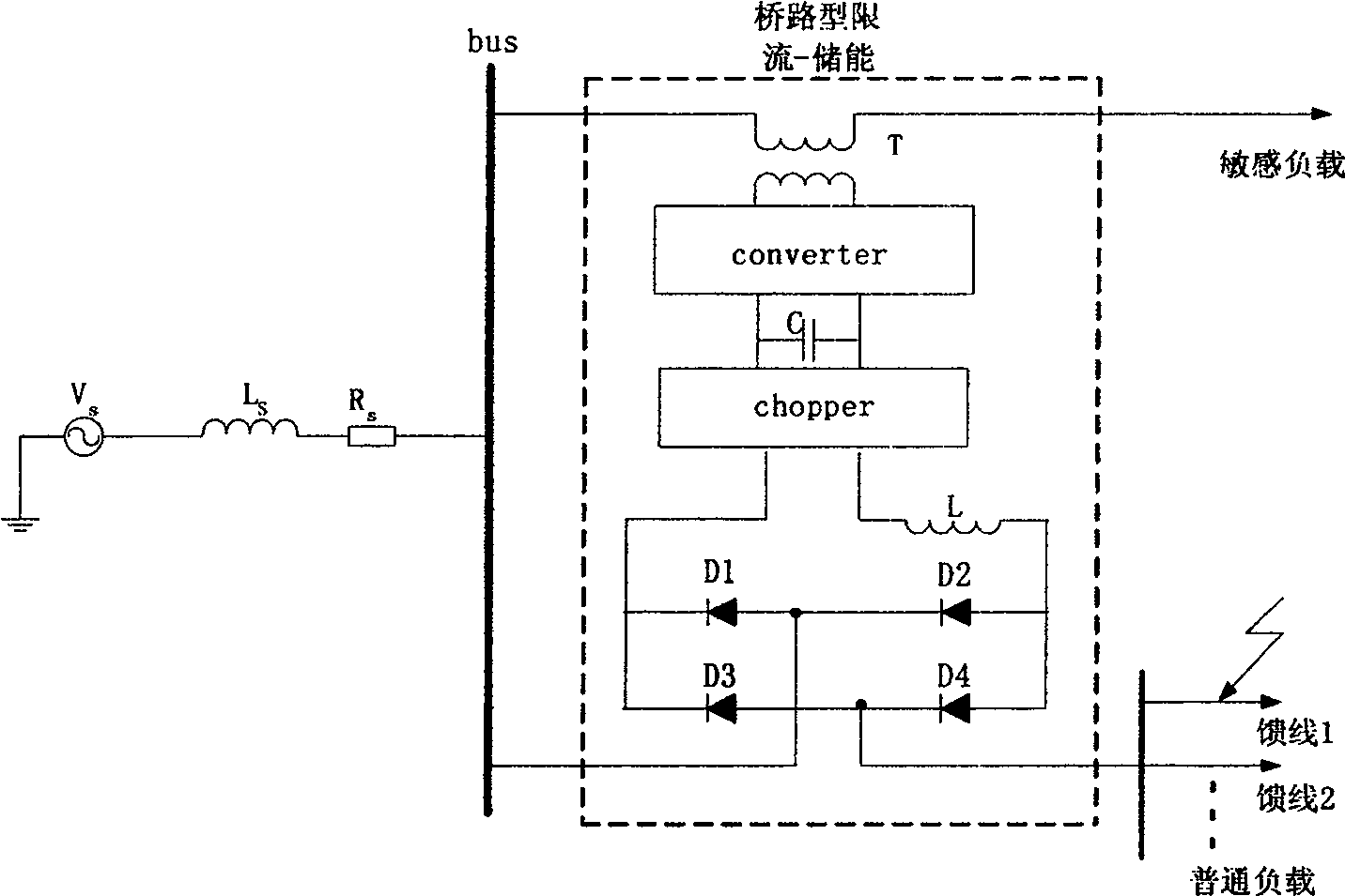
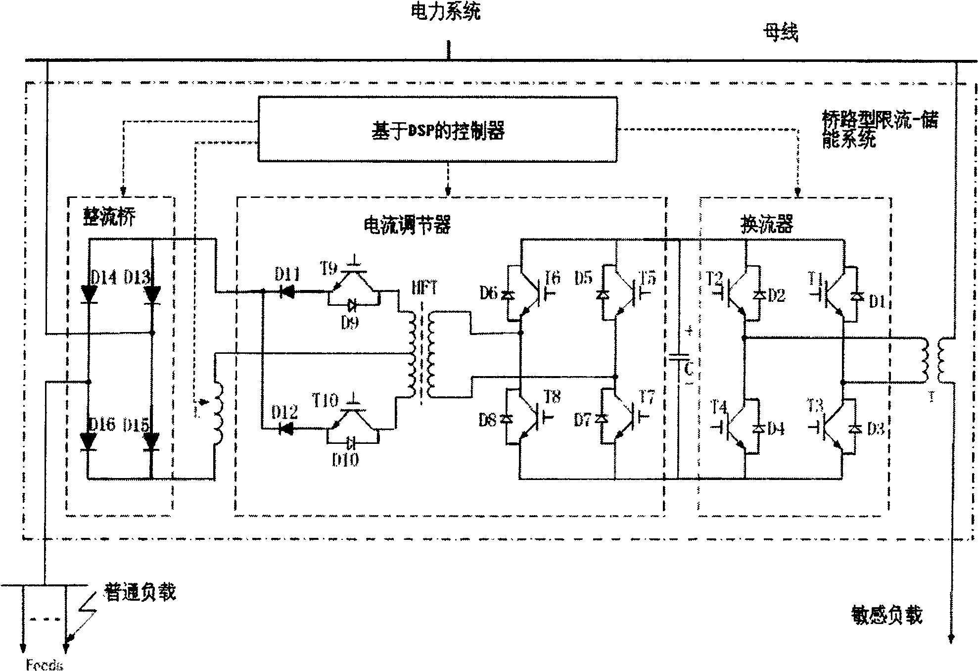
[0013] The bridge type current-limiting energy storage circuit of the present invention is such as figure 1 Shown in the dashed box. The present invention consists of connecting transformer T, converter converter, current regulator chopper, connecting converter and current regulator DC capacitor C, high temperature superconducting coil L, diode rectifier bridge D 1 ~D 4 It is composed of a controller based on a DSP chip. The primary side of the transformer T is connected in series on the sensitive load feeder side, and the secondary side is connected to the AC side of the converter. The DC side of the converter is connected in parallel with the DC capacitor C and the current regulator chopper , The current commutation unit of the current regulator chopper connects the high-temperature superconducting coil L and the diode bridge D 1 ~D 4 On the DC side, diode rectifier ...


PUM


Abstract

The circuit of energy storage includes connection transformer, converter, chopper, DC capacitance, coil of high-temperature superconductor, diode rectification bridge, and controller based on DSP chip. Primary side of transformer is connected to side of sensitive load feeder in series, and secondary side is connected to AC side of converter. Current inversion unit of chopper is connected to DC side of coil and the diode bridge. AC side of the bridge is connected in series to feed line side of general loads. Chopper is composed of current inversion unit, voltage inversion unit, and transformer. Being connected to bus line at exit of AC power system, chopper is connected in series to feed lines from paralleled sensitive load and general load. In normal time, the circuit can adjust asymmetric voltages; carry out filtering, reactive and wattful compensation, and regulating system tidal current. In fault of system, the circuit can limit peak value and steady state value.

Description

Technical field [0001] The invention relates to a bridge type current-limiting energy storage circuit used in a transmission and distribution network. Background technique [0002] Due to the development of the power system, the increase in load, the investment of large-capacity generating units, power plants and substation equipment, especially the emergence of large power plants in the load center and the interconnection of large power systems, the transmission and distribution network capacity has greatly increased, and at the same time The short-circuit current level is increasing day by day, and even the short-circuit current level has exceeded the breaking capacity of current circuit breakers. If no measures are taken to control it, not only will the equipment investment of the new substation increase greatly, but also the original substation equipment in the system will have a great impact, and even a large amount of investment will be needed to transform, rebuild and chan...

Claims


Application Information

Patent Timeline
Patent Type & Authority Patents(China)
IPC IPC(8): H02H9/02H02J3/00H02J3/01H02J3/18H02J15/00
CPCY02E40/69Y02E70/30Y02E40/67Y02E40/30Y02E40/40Y02E40/60
Inventor 赵彩宏黄晓华肖立业林良真余运佳
Owner INST OF ELECTRICAL ENG CHINESE ACAD OF SCI
Learn More