Energy conversion method and device for ultrasonic liquid processing

A technology of liquid processing and transducing devices, applied in the field of ultrasound, which can solve the problems of large number of transducers, low processing capacity, and low ultrasonic field strength, and achieve the effects of simple equipment structure, improved manufacturing, and convenient use

Inactive Publication Date: 2009-09-09
SHENZHEN POLYTECHNIC
6 Cites 0 Cited by

AI-Extracted Technical Summary

Problems solved by technology

This commonly used ultrasonic tank treatment method requires a large number of transducers, and the strength of the ultrasonic field is not high, which cannot meet the processing requirements of some high-intensity ultrasonic tre...

Method used

[0021] In the present invention, the radiating surface of the transducer 3 and the transducer 4 faces the inside of the vibrating tube body 1 along the axial direction. The radiation of the transducer 3 and the transducer 4 sends longitudinal high-frequency energy to the inside of the vibrating tube body 1, causing "cavitation" to occur in the liquid inside the vibrating tube body 1, so that the liquid can be cleaned, emulsified, etc. effect. And the longitudinal high-frequency energy is transformed into the radial direction of the vibrating tube body 1 through the action of the vibrating tube body 1 . Therefore, an...

Abstract

A transducer method for ultrasonic liquid treatment, in which a first transducer and a second transducer are respectively arranged at both ends of a vibrating pipe body, and the length of the vibrating pipe body is selected as the working frequency of the first transducer and the second transducer Corresponding to an integer multiple of the equivalent half-wavelength, the axial vibration of the first transducer and the second transducer is converted into radial vibration, and the ultrasonic energy is converged in the tube to apply strong ultrasonic energy to the liquid in the tube. The transducer device for ultrasonic liquid treatment includes a vibrating tube body, a first transducer, a second transducer arranged at both ends of the vibrating tube body, and an ultrasonic generator for driving the transducer. The vibrating tube body can convert the vibration generated by the transducer along the axial direction of the vibrating tube body into vibration along the radial direction of the vibrating tube body, so that the ultrasonic energy can concentrate on the liquid in the tube. The device of the present invention has simple equipment structure, high reliability and convenient use, and can be widely used in the fields of object cleaning, emulsification, crushing, sonochemistry, extraction of Chinese herbal medicines, bioengineering and the like.

Application Domain

Technology Topic

Image

  • Energy conversion method and device for ultrasonic liquid processing
  • Energy conversion method and device for ultrasonic liquid processing
  • Energy conversion method and device for ultrasonic liquid processing

Examples

  • Experimental program(1)

Example Embodiment

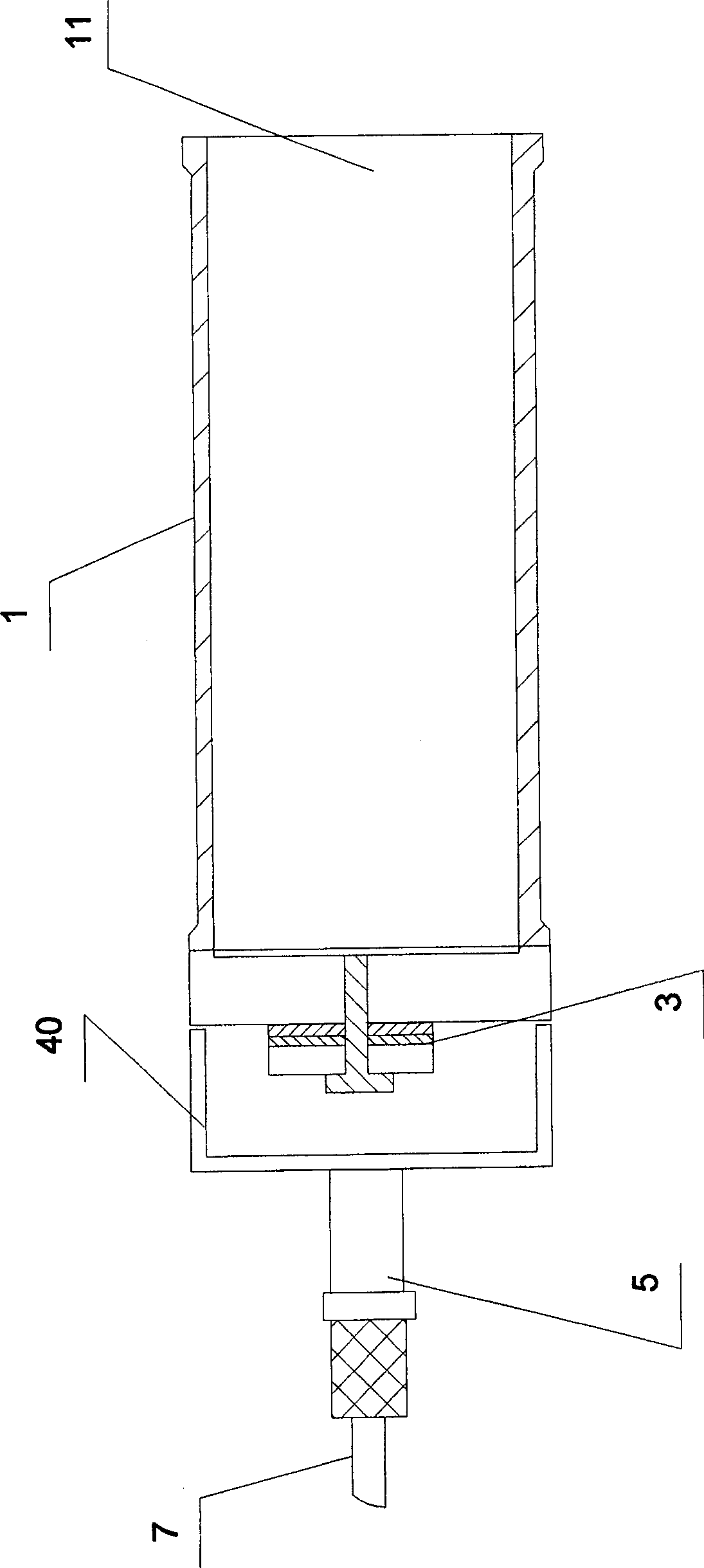
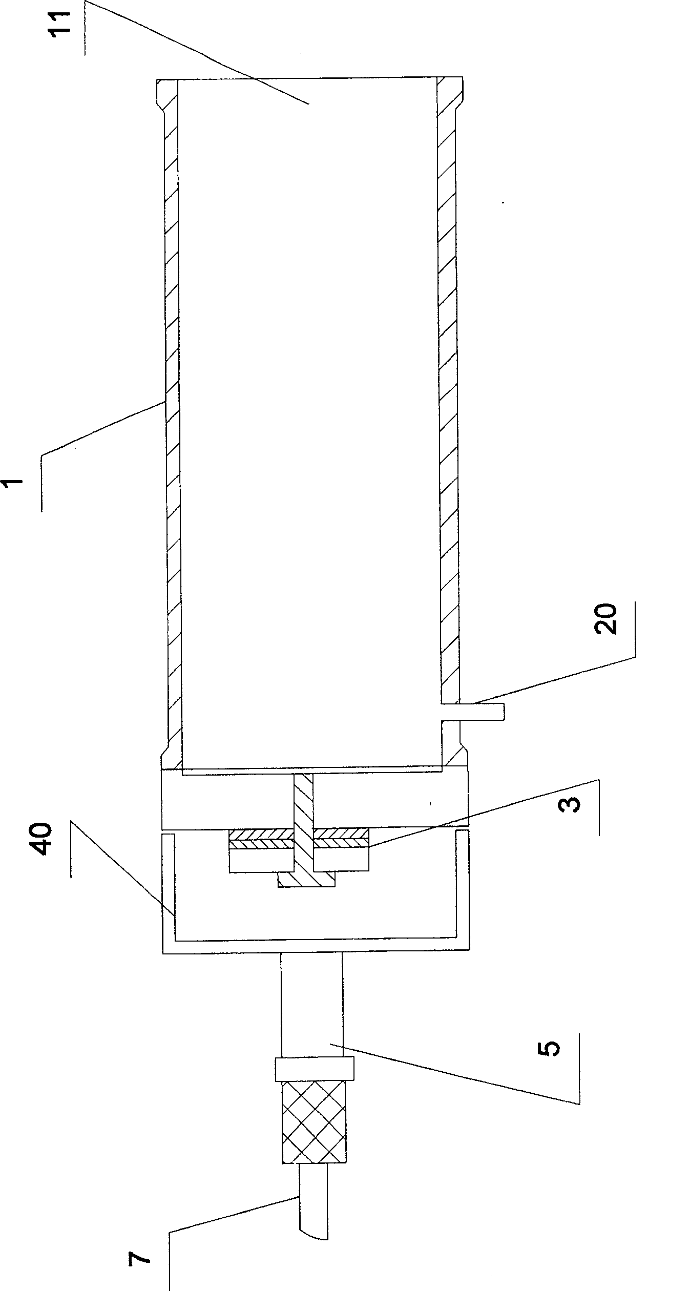
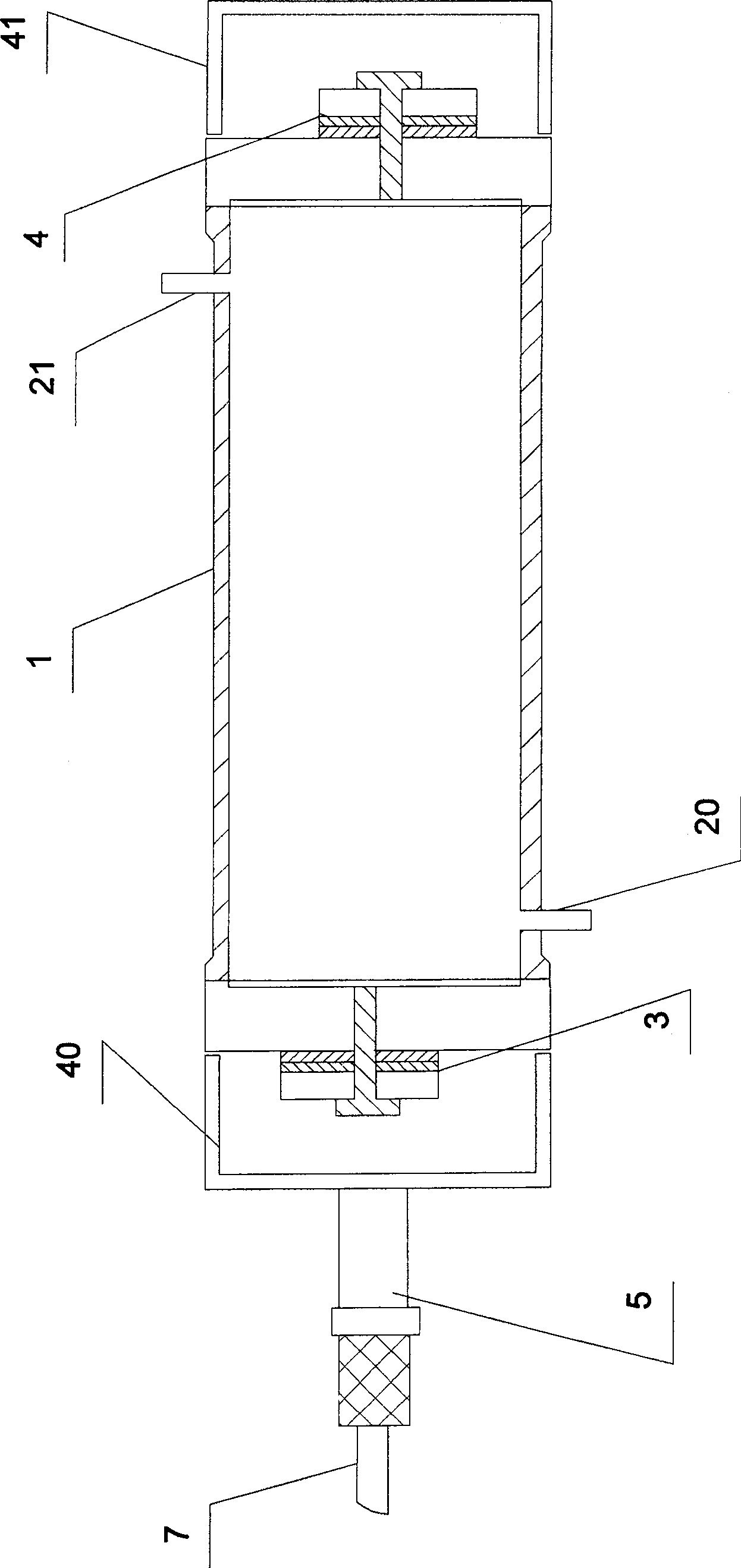
[0016] The invention provides an ultrasonic transducer device for liquid treatment. Such as figure 1 As shown, it is a schematic diagram of the first embodiment of the present invention. The liquid processing ultrasonic transducer includes at least one ultrasonic generator (not shown), a transducer 3, and a vibrating tube body 1 containing liquid. One end of the vibrating tube body 1 is provided with an opening 11, and the other end is equipped with a transducer 3, which is a longitudinal vibration transducer that can convert the ultrasonic waves generated by the ultrasonic generator into longitudinal high-energy mechanical vibration . The transducer 3 is fixedly connected to the vibrating tube body 1 by welding, which can just close the end of the vibrating tube body 1. The transducer 3 is electrically connected to the ultrasonic generator through a cable 7. A sleeve body 40 capable of accommodating the transducer 3 is also provided on the outside of the transducer 3, the upper part of the sleeve body 40 is connected with a waterproof screw 5, and the cable 7 passes through the waterproof screw 5 and is electrically connected to the transducer 3. .
[0017] in figure 1 The most important feature of the ultrasonic liquid treatment transducer disclosed in, is that the selection of the vibrating tube body 1 must follow a certain rule. For example, in this embodiment, the length of the vibrating tube body 1 is an integer multiple of the equivalent half-wavelength corresponding to the working frequency of the transducer 3.
[0018] Such as figure 2 Shown is a schematic diagram of the second embodiment of the present invention. In this embodiment, its basic components are the same as figure 1 It is similar to that disclosed in, but on the side wall of one end of the vibrating tube body 1 where the transducer 3 is connected, a liquid port 20 is provided at a certain distance from the transducer 3. Liquid can flow into or out of the vibrating tube body 1 from the port 20.
[0019] Such as image 3 Shown is a schematic diagram of the third embodiment of the present invention. The invention provides an ultrasonic transducer device for liquid processing. It mainly includes at least one ultrasonic generator (not shown), a transducer 3 and another transducer 4, and a vibrating tube body 1. A transducer 3 and a transducer 4 are respectively installed at both ends of the vibrating tube body 1. The transducer 3 and the transducer 4 may be the same transducer or different transducers. The transducer 3 and the transducer 4 are both fixedly connected to the end of the vibrating tube body 1 by welding, which can just close the two ends of the vibrating tube body 1, so that the vibrating tube body 1 forms a Closed tube body. The transducer 3 and the transducer 4 are electrically connected to the ultrasonic generator through a cable. A sleeve body 40 capable of accommodating the transducer 3 is provided on the outside of the transducer 3. The upper part of the sleeve body 40 is connected with a waterproof screw 5, and the cable 7 passes through the waterproof screw 5 and is electrically connected to the transducer 3. A sleeve body 41 capable of accommodating the transducer 4 is provided on the outside of the transducer 4. A liquid inlet 20 and a liquid outlet 21 are provided on the side walls of the vibrating tube 1 at a certain distance from the transducers 3 and 4 at a certain distance. Liquid can flow in from the liquid inlet 20. After being processed inside the vibrating tube 1, It flows out from the liquid outlet 21.
[0020] In the present invention, the working frequency of the transducer 3 or the transducer 4 is generally between 20KHZ and 40KHZ, and the length of the vibrating tube body 1 can generally be selected between 30CM and 2M, but it is not limited to this. Generally, it is an integer multiple of the half-wavelength of the working frequency of the transducer 3 or the transducer 4. The diameter of the vibrating tube body 1 can be determined according to the specific use of the ultrasonic liquid treatment transducer, and it can also be designed to satisfy a certain relationship with the frequency.
[0021] In the present invention, the radiation surfaces of the transducer 3 and the transducer 4 face the inside of the vibrating tube 1 in the axial direction. The radiation of the transducer 3 and the transducer 4 sends longitudinal high-frequency energy to the inside of the vibrating tube 1, causing "cavitation" in the liquid inside the vibrating tube 1, so that the liquid can achieve cleaning, emulsification, etc. effect. And the longitudinal high frequency energy is transformed into the radial direction of the vibrating tube 1 through the action of the vibrating tube body 1. As a result, an inward converging effect is formed, and the closer to the middle of the vibrating tube body 1, the stronger the inward converging effect. Therefore, a very high intensity ultrasonic field is obtained inside the vibrating tube body 1. In addition, the ultrasonic liquid treatment transducer of the present invention adopts one or two transducers, and the device structure is simple, which is beneficial to manufacturing and improving the stability and reliability of the device. Secondly, the length and diameter of the vibrating tube body can be designed according to needs, which is convenient to use.
[0022] The ultrasonic liquid treatment transducer of the present invention can be widely used in various fields including cleaning, emulsification, crushing, sonochemistry, Chinese herbal medicine extraction, and bioengineering of objects.

PUM

no PUM

Description & Claims & Application Information

We can also present the details of the Description, Claims and Application information to help users get a comprehensive understanding of the technical details of the patent, such as background art, summary of invention, brief description of drawings, description of embodiments, and other original content. On the other hand, users can also determine the specific scope of protection of the technology through the list of claims; as well as understand the changes in the life cycle of the technology with the presentation of the patent timeline. Login to view more.

Similar technology patents

Process for preparing 1,1,2 trichloroethylane

ActiveCN1793093ASimple equipment structureEasy to operatePreparation by halogen additionMain channelChemistry
Owner:SHANGHAI CHLOR ALKALI CHEM

Classification and recommendation of technical efficacy words

  • Facilitate manufacturing
  • Simple equipment structure

Preparation process of ceramic roller rod

Owner:广东金刚新材料有限公司 +1
Why Eureka
Try Eureka