
Double swirl-flow combustion apparatus for industrial boiler and kiln

A technology for industrial boilers and combustion devices, applied in combustion equipment, solid fuel combustion, lighting and heating equipment, etc., can solve the problems of environmental protection benefits that cannot balance economic waste and energy waste, energy waste, etc.

Inactive Publication Date: 2009-09-09
王树洲
View PDF5 Cites 0 Cited by
  • Summary
  • Abstract
  • Description
  • Claims
  • Application Information

AI Technical Summary

Problems solved by technology

[0018] It can be seen that the energy utilization mode of the gas furnace is completely an energy waste mode, and the environmental protection benefits it receives cannot balance the economic waste and energy waste caused by it.

Method used


Image

  • Double swirl-flow combustion apparatus for industrial boiler and kiln
  • Double swirl-flow combustion apparatus for industrial boiler and kiln
  • Double swirl-flow combustion apparatus for industrial boiler and kiln

Examples


Embodiment Construction

[0089] The present invention will be further described in conjunction with the accompanying drawings of the above-mentioned embodiments.

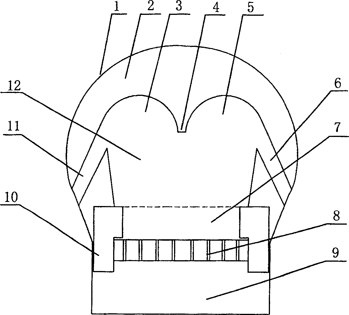
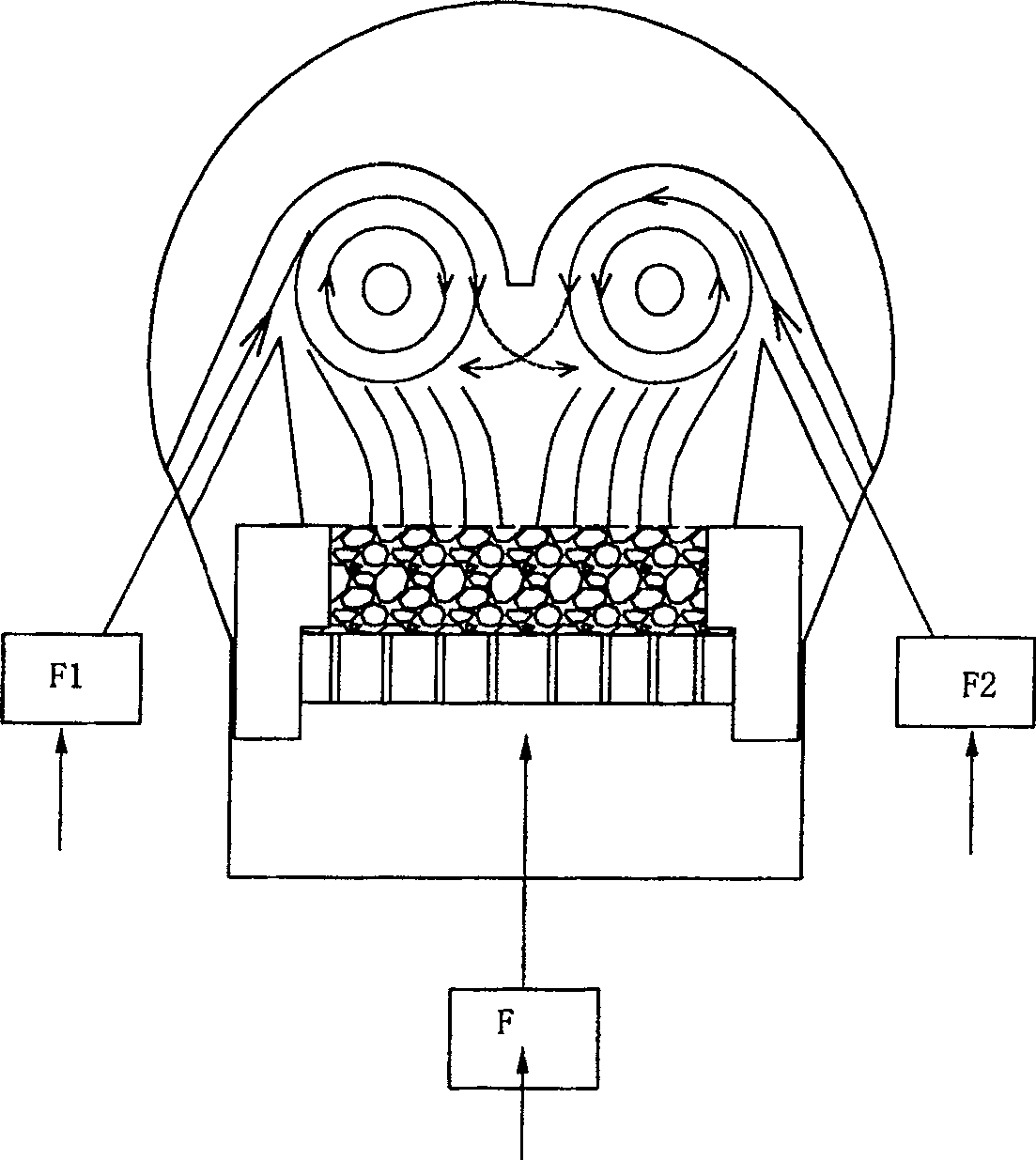
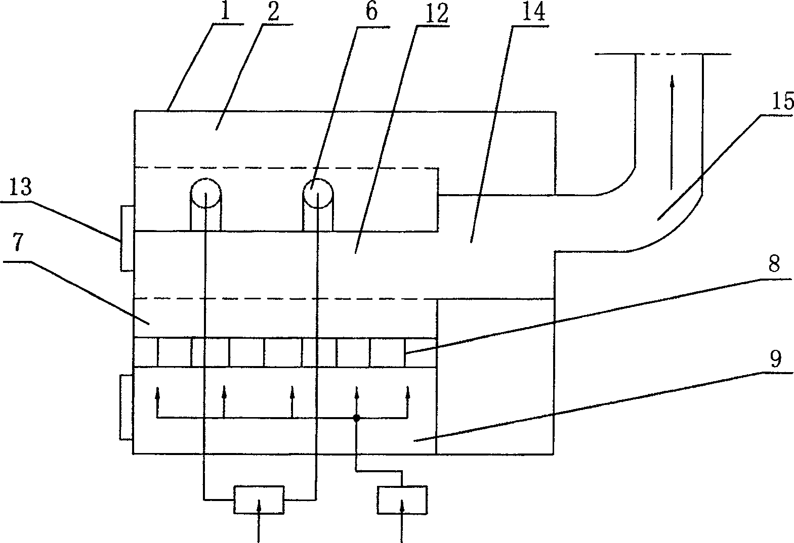
[0090] Such as figure 1 , 3 Shown, the industrial boiler of the present invention, kiln double swirl combustion device, comprise combustion hearth 12, fire grate 8, coal inlet 13 and high-temperature gas outlet 15, the top of its furnace hearth 12 cross-sections is to form double swirl The semicircles of the flow combustion areas 3 and 5 are connected with double arches, and the two sides of the furnace 12 are equipped with tubular combustion-supporting tuyeres 11 and 6 leading to the furnace. A turbulent combustion zone 14 is provided between 12 and the high-temperature gas outlet 15 .

[0091] The working principle is as follows: figure 2 As shown, during the combustion operation, the combustion-supporting air is tangentially injected into the two swirl combustion zones from the combustion-supporting tuyeres 11 and 6 on both sides of ...


PUM


Abstract

The invention relates to a double-swirl combustion device for industrial boilers and kilns, which includes a combustion furnace, a fire grate, a coal filling port and a high-temperature gas outlet. Arched, the two sides of the furnace are equipped with combustion-supporting air outlets leading to the furnace, and the rear of the furnace is connected to the high-temperature gas outlet. Add turbulent combustion zone. Simple structure, small size, high power, full combustion, high thermal efficiency, low energy consumption, remarkable coal-saving effect, no environmental pollution, completely solve the problem of coal-burning pollution, and its popularization and application will obtain huge economic and social benefits. The invention has good docking performance with existing boilers and kilns, and is not only suitable for new construction and direct production of new products, but also suitable for the transformation of existing industrial boilers and industrial kilns, and can also be applied to other suitable heating fields.

Description

technical field [0001] The invention relates to an improved coal-fired combustion device, which is mainly used in industrial boilers and kilns, and belongs to thermal facilities. Background technique [0002] Today, no matter how highly civilized and developed human society and science and technology are, people are helpless when faced with the problem of energy depletion. So far, there is no new technology available to solve the problem. this problem. [0003] The report released by the United Nations on January 24, 1994 announced to the world that based on the proven global mineral reserves plus the possible increase in reserves, oil can still be mined for 75 years, natural gas can only be mined for 56 years, and coal can be mined for 42 years. Coupled with the rapid growth of the world's population and the continuous improvement of living standards, this mining life will decrease by a certain percentage. Therefore, in the second half of the 21st century, that is, after 2...

Claims


Application Information

Patent Timeline
Patent Type & Authority Patents(China)
IPC IPC(8): F23B90/00F23B60/00F23B90/04
Inventor 吴俊恩王树洲
Owner 王树洲
Learn More