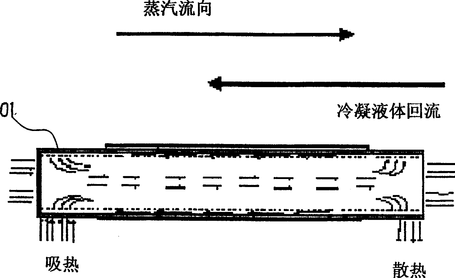
Heat pipe

A technology of heat pipes and copper pipes, which is applied in the field of computer accessories, can solve problems such as hindering water return flow, broken water flow, and weak pipe structure, so as to avoid excessive fusion, increase water flow space, and reduce manufacturing risks.

Inactive Publication Date: 2009-09-23
杨开艳
View PDF6 Cites 0 Cited by
  • Summary
  • Abstract
  • Description
  • Claims
  • Application Information

AI Technical Summary

Problems solved by technology

Because the copper ball will be fused due to cohesion after melting, if the control is not good, it will easily cause the pores in some places to be larger, while the pores in some places will be narrower, thereby hindering the capillary action of water backflow or appearing due to insufficient sintering. lead to structural fragility of the heat pipe
In addition, after the heat pipe is bent or flattened, the welding interface will be cracked, which will also hinder the return of water
[0007] It is difficult to fully inspect the thermal resistance performance of heat pipe products, because the measurement time of a product is too long, so it can only be carried out by random inspection
However, the random inspection can only represent the overall level, and there are still a small number of products that are over-sintered and the pores are too small, which makes the capillary phenomenon not good and the performance declines; or the fusion is insufficient and the structure of the catheter is fragile.
[0008] On the other hand, many heat pipes must be bent or flattened. This process will generate stress on the sintered copper ball powder, and some will break immediately, resulting in poor water flow; and some will break after being delivered to the user for a period of time. Phenomenon, causing overheating of the server products where the heat pipe is located or the multimedia computer with a huge workload

Method used


Image

  • Heat pipe
  • Heat pipe
  • Heat pipe

Examples


Embodiment Construction

[0022] The following descriptions are only preferred embodiments embodying the principles of the present invention, and do not therefore limit the protection scope of the present invention.

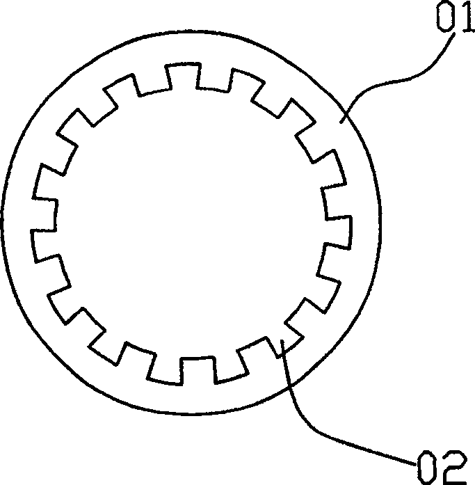
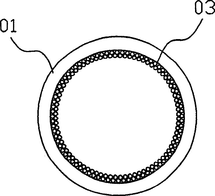
[0023] As shown in accompanying drawing 3: the heat pipe of the present invention has a hollow copper tube 10, a copper ball powder layer 20 is sintered in the copper tube 10, and a layer of copper ball powder layer 20 is attached to the inner wall of the copper tube 10 below 800 ℃. Copper produces an insulating layer 30 for sintering reaction, and the copper ball powder layer 20 and the copper tube 10 can be separated from each other.

[0024] The structure and manufacturing process of the present invention are different from general heat pipes. Traditional heat pipes are sintered together with copper ball powder, which is integrally sintered. However, the present invention first attaches a layer of barrier layer 30 to the inner wall of the copper tube 10, so that the copper ball powder ...


PUM

PropertyMeasurementUnit
thicknessaaaaaaaaaa
thicknessaaaaaaaaaa
thicknessaaaaaaaaaa

Abstract

The invention relates to the technical field of computer accessories, in particular to a heat pipe inside a computer radiator. The heat pipe has a hollow copper tube, and a copper ball powder layer is sintered in the copper tube, which contains various inorganic salt balls that are easy to absorb water, and different sections of the copper tube have different addition ratios. The inner wall of the copper tube has an insulating layer which does not sinter with copper at temperatures below 800° C., so that the copper ball powder layer and the copper tube are not sintered. Due to the presence of an insulating layer on the inner wall of the copper tube, the sintered copper ball powder and the copper tube become separate entities. Forming a thin layer of voids as a water flow channel can increase the water storage capacity, make the water flow smooth, and reduce the stress during bending or flattening to avoid fracture.

Description

Technical field: [0001] The invention relates to the technical field of computer accessories, in particular to a heat pipe inside a computer radiator. Background technique: [0002] The calculation speed of the current electronic product chips is getting faster and faster, so the radiators used are gradually unable to meet the demand. In order to improve the heat dissipation rate of the metal sheet of the radiator, many radiators are currently equipped with heat pipes to improve heat conduction rate. [0003] As shown in accompanying drawing 1, the principle of the heat pipe is: a copper tube 01 sealed at both ends has a layer of medium (wick) that enables the liquid to transport the liquid by capillary action. When the liquid at the heating end is vaporized, along the From the central space to the cooling end, it is cooled to liquid again, and then returns to the heating end along the conveying medium along the inner edge, so that the purpose of rapid heat transfer can be ...

Claims


Application Information

Patent Timeline
Patent Type & Authority Patents(China)
IPC IPC(8): F28D15/04G06F1/20
CPCF28D15/046
Inventor 陈弘岳
Owner 杨开艳
Why Eureka
Try Eureka