
Method for manufacturing formed honeycomb structure

A manufacturing method and technology of formed bodies, applied in the direction of separation methods, chemical instruments and methods, ceramic products, etc., can solve the problems of using multiple products, insufficient mixing of forming raw materials, waste of forming raw materials25, etc., and achieve the goal of reducing the impact Effect

Inactive Publication Date: 2009-09-30
NGK INSULATORS LTD
View PDF4 Cites 0 Cited by
  • Summary
  • Abstract
  • Description
  • Claims
  • Application Information

AI Technical Summary

Problems solved by technology

[0028] In this way, in the conventional manufacturing method of the honeycomb formed body, when the molding raw material 25a is added afterward and the molding is performed as the molding raw material 25 filled in the molding machine 21 decreases, the molding raw material 25b filled earlier is included. Since the molded body of the boundary portion 28 with the post-filled molding material 25a cannot be used as a plurality of products, there is a problem that the molding material 25 is wasted until all the molding material 25 including the boundary portion 28 is extruded.
[0029] Moreover, in continuous extrusion molding, since there is no need to post-fill such molding raw materials, the boundary portion of the raw materials will not be formed. However, since the kneading process is completed by the built-in screw, the kneading of the molding raw materials is insufficient. , It is difficult to give the molding raw material viscosity. In order to improve the viscosity and ensure the formability, in order to strengthen the kneading function, there is a problem that it is necessary to increase the equipment capacity and add excess binder to the molding raw material, thereby increasing the cost.
[0030] In addition, as the outer diameter of honeycomb molding increases, there is a problem of enlarging the equipment in order to ensure extrusion pressure

Method used


Image

  • Method for manufacturing formed honeycomb structure
  • Method for manufacturing formed honeycomb structure
  • Method for manufacturing formed honeycomb structure

Examples


Embodiment Construction

[0058] Although the embodiment of the manufacturing method of the honeycomb formed body of the present invention will be described in detail below with reference to the drawings, the present invention is not limited thereto, and various changes can be made according to the knowledge of those skilled in the art without departing from the scope of the present invention. , modify, improve.

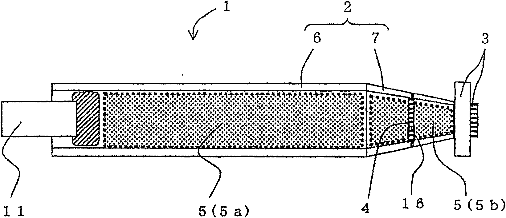
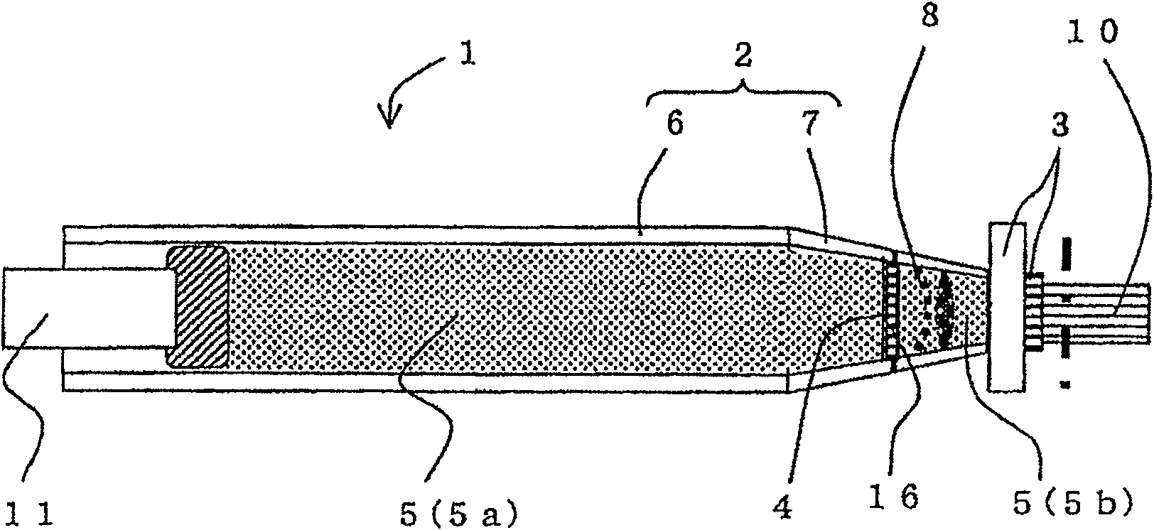
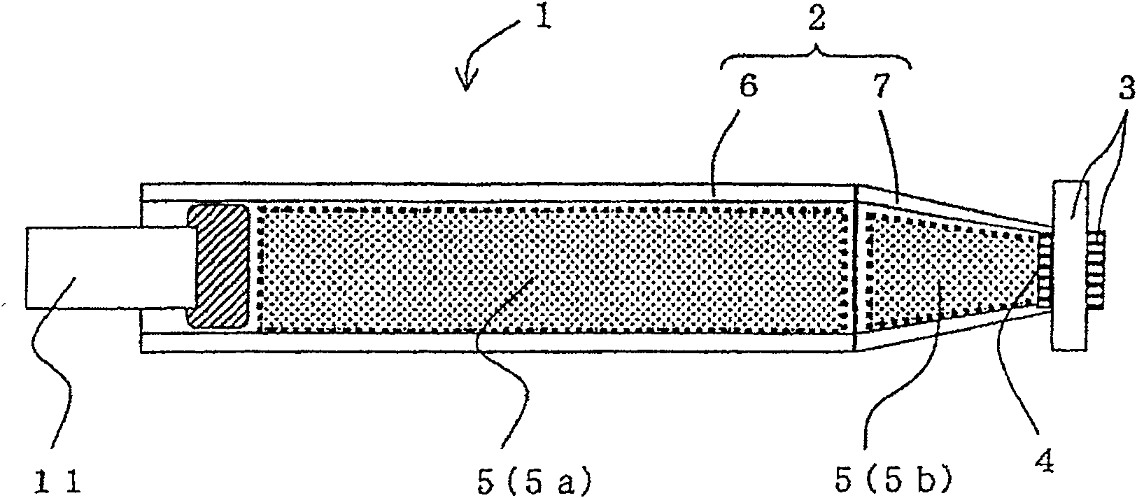
[0059] FIG. 1( a ) and FIG. 1( b ) are explanatory views schematically showing an example of a step of extrusion molding a raw material in one embodiment of the method for producing a formed honeycomb article of the present invention.

[0060] The manufacturing method of the formed honeycomb body of this embodiment is a method of manufacturing a formed honeycomb body which can be realized using the forming machine 1 shown in FIG. 1( a ) and FIG. 1( b ).

[0061] The molding machine 1 is a plunger type molding machine including a cylindrical body 6 and a barrel 7 constituting a molding raw mat...


PUM

PropertyMeasurementUnit
porosityaaaaaaaaaa
porosityaaaaaaaaaa
porosityaaaaaaaaaa

Abstract

The present invention provides a method for producing a formed honeycomb body that can effectively use a forming raw material filled in a forming machine. The manufacturing method of the formed honeycomb body of the present invention is that the forming raw material pipeline (2) with the metal cover (3) for forming the formed honeycomb body disposed on one end is filled with the forming material (5), and the filled forming material is (5) A method of manufacturing a honeycomb formed body (10) obtained by extruding and forming a honeycomb formed body (10) from a metal cover (3) for forming a honeycomb formed body. A filter (4) for filtering foreign substances contained in the forming material (5) is arranged near the metal cover (3) for forming the formed body, and an operation is performed to reduce the frictional resistance between the inner surface of the forming material pipe (2) and the forming material (5) A method for producing a formed honeycomb body to obtain a formed honeycomb body (10).

Description

technical field [0001] The present invention relates to a method for producing a formed honeycomb body. More specifically, it relates to reducing the influence of the boundary portion of the molding raw material filled first and the molding raw material filled later on the molding in the case of subsequently adding the molding raw material to perform molding as the molding raw material filled into the molding machine decreases. A method of manufacturing a honeycomb formed body that can effectively use the forming raw material filled in the forming machine. Background technique [0002] As a filter (diesel particulate filter (DPF)) for trapping and removing particulate matter contained in dusty fluids such as diesel engine exhaust, or as a catalyst component for carrying and purifying harmful substances in exhaust gas ( As the catalyst carrier for purifying exhaust gas, a formed honeycomb body having partition walls forming a composite of a plurality of adjacent cells is wid...

Claims


Application Information

Patent Timeline
Patent Type & Authority Patents(China)
IPC IPC(8): B01D39/20F01N3/02C04B38/00
Inventor 市川结辉人
Owner NGK INSULATORS LTD
Learn More