Silencer for fuel cell
A fuel cell and muffler technology, which is applied in the direction of fuel cells, fuel cell additives, and muffler devices, and can solve the problems of reduced muffler performance, etc.
- Summary
- Abstract
- Description
- Claims
- Application Information
AI Technical Summary
Problems solved by technology
Method used
Image

Examples
no. 1 example
[0063] use Figure 30 The exhaust system of the fuel cell system to which the muffler 10 of this embodiment is applied will be briefly described. The fuel cell system 80 has a fuel cell 82, a hydrogen tank 84 that supplies hydrogen gas to the fuel cell 82, a blower 86 that supplies an oxidizing gas to the fuel cell 82, and an exhaust system 88 that discharges exhaust gas from the fuel cell 82 (in Figure 30 indicated by a double-dotted line).
[0064] The hydrogen tank 84 is connected to the fuel cell 82 through a fuel gas supply channel 85 , and the flow of hydrogen (fuel gas) stored in the hydrogen tank 84 is adjusted by a regulator 90 and supplied to the fuel cell 82 through a control valve 92 . On the other hand, the blower 86 is connected to the fuel cell 82 through an oxidizing gas supply passage 87 , and supplies oxidizing gas (air) to the fuel cell 82 . In the fuel cell 82, the supplied hydrogen gas reacts with the air to generate electric power, and at the same time...
no. 2 example
[0081] use Figure 6The muffler 10b of this embodiment will be described. exist Figure 6 shown in figure 1 The shape of the sound hole on the muffler shown in the Figure 7 The shape of the sound transmission hole on the muffler of the modified example is shown in Figure 8 The shapes of the sound transmission holes in the silencer of other modified examples are shown in . Regarding the muffler 10b of the present embodiment, the shape of the sound transmission hole formed on the inner pipe is different from that of the muffler 10 of the first embodiment, which will be described in detail below. In addition, for the same structure as the muffler 10 of the first embodiment, the same reference numerals are used and descriptions thereof are omitted.
[0082] In this embodiment, the sound transmission hole 18b is formed as Figure 6 Ellipse shape shown in solid line. The shape of the ellipse will be Figure 6 The envelope shape of the circle group produced by sliding the ...
no. 3 example
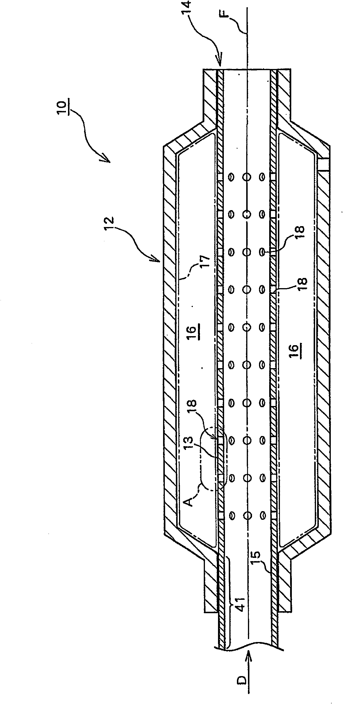
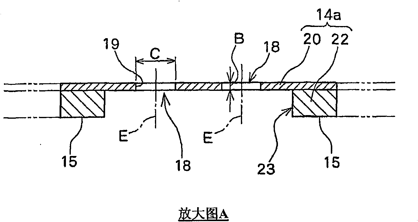
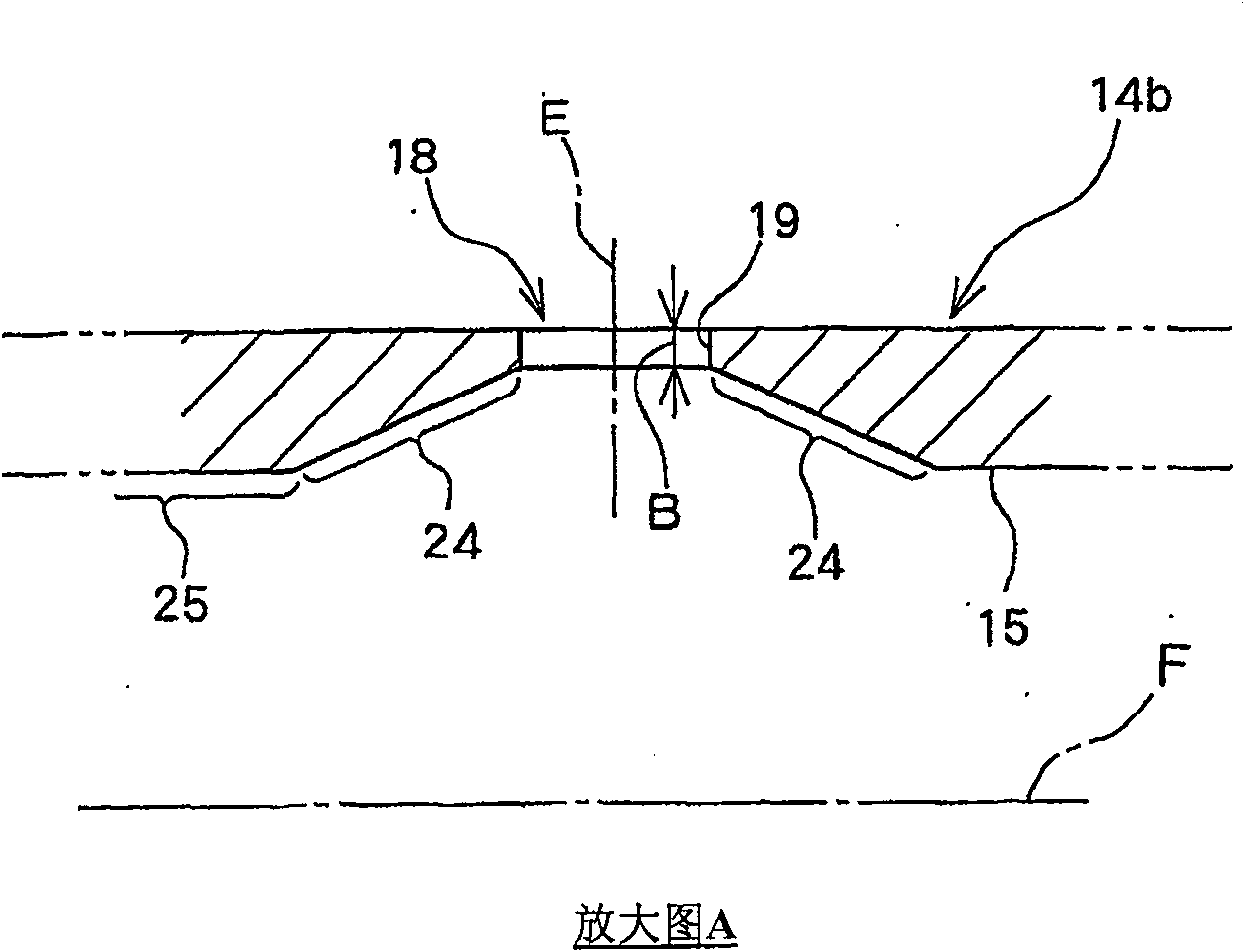
[0093] use Figure 9 The muffler 10c of this embodiment will be described. exist Figure 9 shown in figure 1 An enlarged cut view of the inner tube wall surrounded by double-dashed line A in . The muffler 10c of this embodiment differs from the muffler 10 of the first embodiment in that the sound-permeable holes are waterproofed, and will be described in detail below. In addition, the same code|symbol is used for the same structure as the muffler 10 of 1st Example, and description is abbreviate|omitted.
[0094] In this example, if Figure 9 As shown, a waterproof layer 34 is formed on the inner wall 19d of the sound transmission hole 18 . In order to form the waterproof layer 34, a waterproof film such as vinyl fluoride resin is formed on the inner wall 19d. In addition, the waterproof layer 34 may be formed not only on the inner wall 19d of the sound transmission hole, but also on the entire inner tube 14d. Processes required for waterproofing can be simplified by tr...
PUM
 Abstract
Description
Claims
Application Information
 - R&D
- Intellectual Property
- Life Sciences
- Materials
- Tech Scout
- Unparalleled Data Quality
- Higher Quality Content
- 60% Fewer Hallucinations
Browse by: Latest US Patents, China's latest patents, Technical Efficacy Thesaurus, Application Domain, Technology Topic, Popular Technical Reports.
© 2025 PatSnap. All rights reserved.Legal|Privacy policy|Modern Slavery Act Transparency Statement|Sitemap|About US| Contact US: help@patsnap.com