
Forming method of spiral subsection blade

A molding method and blade technology, which is applied in the field of pressure processing, can solve the problems that the molding capacity of the press cannot meet the pressing requirements of segmented blades, cannot manufacture equal-thickness spiral blades, and the thickness of the spiral blades is uneven, so as to improve the utilization rate of materials, The effect of reduced driving power and small residual deformation

Active Publication Date: 2009-10-28
ZHENJIANG BANGHE SPIRAL MFG
View PDF7 Cites 1 Cited by
  • Summary
  • Abstract
  • Description
  • Claims
  • Application Information

AI Technical Summary

Problems solved by technology

[0003] (1) The blank is prepared by cutting and blanking the steel plate. First, the blank is welded piece by piece to form a barrel-shaped segment body, and then one end of the segment body is welded to position on the transmission shaft, and the other end is pulled with a high-power The equipment is stretched into helical body segments, and then the helical body segments are welded segment by segment to form the final helical blade. This method has low production efficiency, labor and time-consuming, poor manufacturing accuracy, and the pitch error of the helical blade is more than 10%.
[0004] (2) Use a mold on the press to press the blank into a spiral segmented blade at one time. This method must use a large press, the equipment is expensive, and the manufacturing cost is high, especially when forming blades with large diameters and thicknesses. General presses The molding capacity of the blade cannot meet the pressing requirements of the segmented blades; in addition, the molding of a spiral segmented blade of a specification requires a matching mold. The investment is very large, and the included angle between the starting end face and the ending end face of the pressed helical segmented blade perpendicular to the projection of the axis of the helical plane is less than 360°
[0007] Both of these two patents disclose forming equipment for manufacturing spiral blades by continuous rolling. This manufacturing method has the advantages of high material utilization and high production efficiency. However, the outer edge of the spiral blade manufactured by the continuous rolling method is thinner. Thick, the thickness of the spiral blade is uneven, because the rolling deformation force required for the spiral blade in the rolling forming process is very large, this method and its forming equipment can only manufacture small diameter and small thickness spiral blades, and the forming accuracy Poor, unable to manufacture spiral blades of equal thickness; unable to meet the spiral forming of large diameter, large thickness materials, high hardness materials and stainless steel materials, and only suitable for mass production of spiral blades

Method used


Image

  • Forming method of spiral subsection blade
  • Forming method of spiral subsection blade
  • Forming method of spiral subsection blade

Examples


Embodiment Construction

[0031] The present invention will be further described below in conjunction with drawings and embodiments.

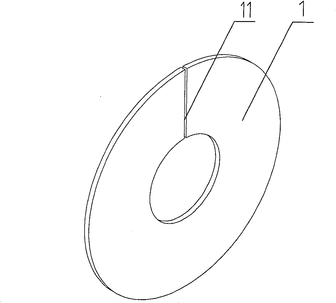
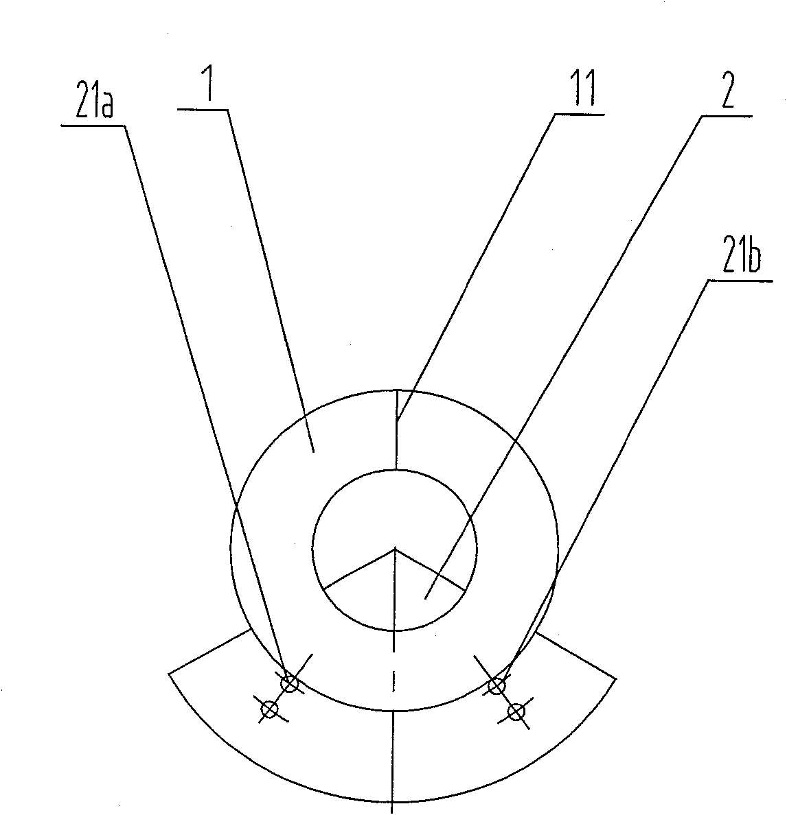
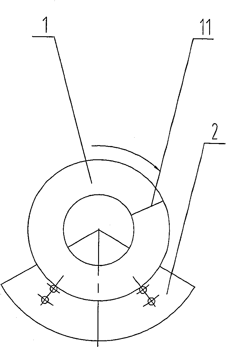
[0032] The ring blank that the present invention adopts is as figure 1 As shown, a straight slit 11 is cut between the radial inner hole and the outer circle of the ring 1 . The blank preparation of the present invention is according to the size requirements of the required spiral blades, the plate is first made into a circular ring blank 1 by CNC flame cutting or plasma cutting, and then according to the radial direction of the circular ring, in the inner hole of the circular ring Cut a straight slit 11 between the outer circle and the outer circle, and the formed blank annulus is close to 360°. When the existing integral molded blank is formed into spiral segmented blades, fan-shaped gaps must be cut out on the ring surface of the circular ring blank, and the fan-shaped ring surface of the formed blank is less than 360°. Obviously, the blank area of ​​the latter is s...


PUM


Abstract

The invention relates to a method for forming spiral segmented blades. In the method, the plate is first cut into a ring blank, and a straight slit is cut between the inner hole and the outer circle of the ring according to the radial direction of the ring. The outer circle of the blank is positioned, the part of the ring blank is molded, and the partial helical surface is molded out of the partial ring blank. After multiple rotations and multiple local moldings, the helical segmented blade Molded finish. The invention greatly reduces the forming force required for the helical segmented blade, the size of the mold used is small, and the energy consumption of the equipment is low. The helical blade product made by the invention has a continuous spiral radian, smooth surface, precise forming and uniform thickness. A mold can be used to produce multiple specifications of spiral segmented blades, the production cost is greatly reduced, and high-strength and high-hardness material spiral segmented blades can be manufactured.

Description

technical field [0001] The invention relates to a molding method of a helical blade, in particular to a method of molding a part of a helical segmented blade, and belongs to the technical field of pressure processing. Background technique [0002] As an accessory of material conveying machinery, spiral blades are widely used. At present, there are two main methods of forming spiral segmented blades: [0003] (1) The blank is prepared by cutting and blanking the steel plate. First, the blank is welded piece by piece to form a barrel-shaped segment body, and then one end of the segment body is welded to position on the transmission shaft, and the other end is pulled with a high-power The equipment is stretched into helical body segments, and then the helical body segments are welded one by one to form the final helical blade. This method has low production efficiency, labor and time-consuming, poor manufacturing accuracy, and the pitch error of the helical blade is more than 1...

Claims


Application Information

Patent Timeline
Patent Type & Authority Patents(China)
IPC IPC(8): B21D53/78
Inventor 李悦
Owner ZHENJIANG BANGHE SPIRAL MFG
Learn More