
Broad band impedance measurement apparatus

An impedance measurement and broadband technology, applied in the field of broadband impedance measurement devices, can solve problems such as increasing the difficulty of PCB design, inability to complete wiring, affecting design quality, etc., and achieves the effects of flexible testing, good mobility, and low cost

Inactive Publication Date: 2009-10-28
ZTE CORP
View PDF6 Cites 0 Cited by
  • Summary
  • Abstract
  • Description
  • Claims
  • Application Information

AI Technical Summary

Problems solved by technology

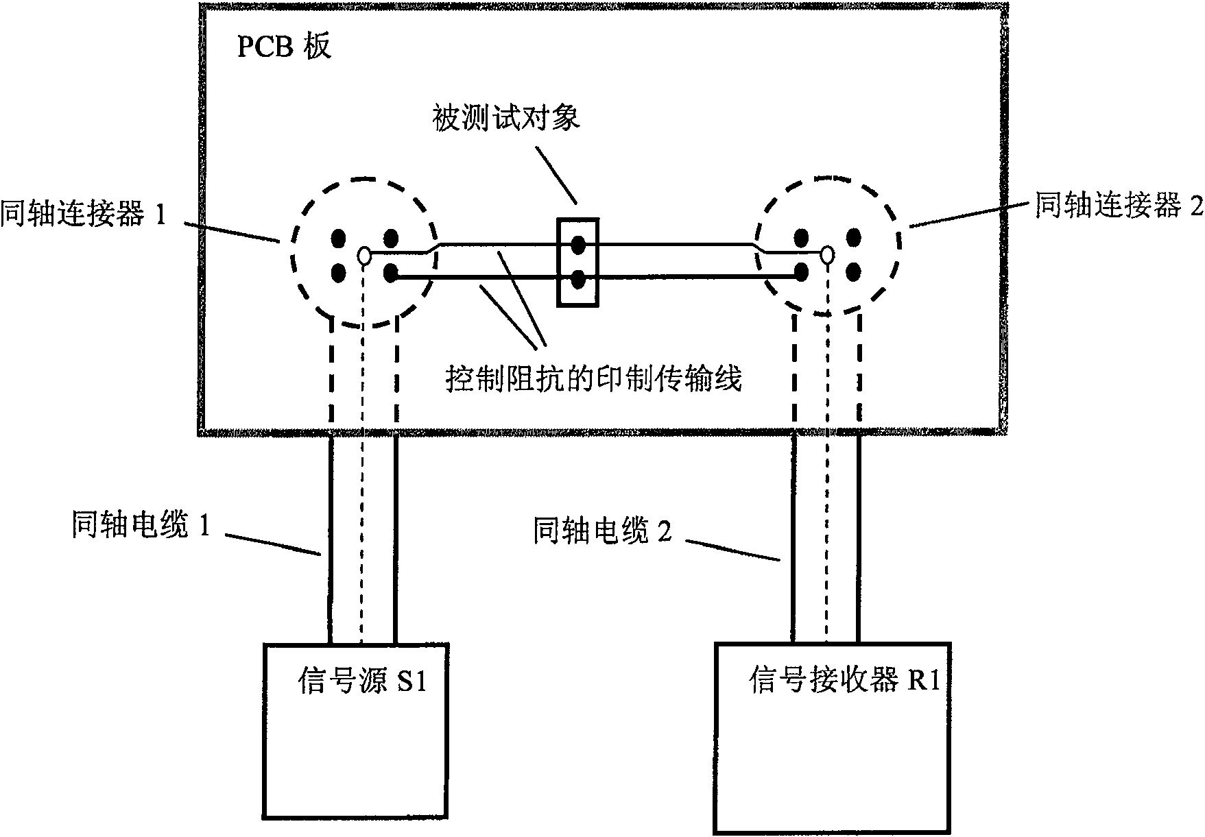
Because the circuit boards that require impedance analysis are generally complex single boards with fast speed, large capacity, and high density, reserving the position of the coaxial connector and auxiliary printed lines for each test point that may need to analyze impedance will Due to the severe shortage of space, the design difficulty of PCB is increased, the design quality is affected, and even the wiring cannot be completed at all.
In addition, when this method is used to measure the impedance between the mutually coupled power and ground planes, it will also cause large errors due to the insertion of parallel plate capacitors formed between the planes between the two coaxial connectors.

Method used


Image

  • Broad band impedance measurement apparatus
  • Broad band impedance measurement apparatus
  • Broad band impedance measurement apparatus

Examples


Embodiment Construction

[0018] Below, refer to the attached Figure 5-7 The broadband impedance measuring device of the present invention will be described in detail.

[0019] The present invention adopts two sections of transmission lines with uniform characteristic impedance (for example, a coaxial cable with a characteristic impedance of 50 ohms), forms a broadband impedance test probe by soldering, and replaces the coaxial connectors and auxiliary PCB, such as Figure 5 Shown is a schematic diagram of the broadband impedance testing device of the present invention. Figure 5 One end of the coaxial cable 1 is connected to the signal source S1 through a connector, and the other end is connected to the coaxial cable 2 through soldering; the other end of the coaxial cable 2 is connected to the signal receiver R1. Through the signal output by the signal source S1 and the signal received by the signal receiver R1, the S21 parameter in the required frequency band can be obtained, and substituted into ...


PUM


Abstract

The invention provides a broadband impedance measurement device, which includes a signal generator, a signal receiver, and two sections of coaxial cables, wherein one end of the first coaxial cable is connected to the signal generator, and one end of the second coaxial cable is connected to the said signal generator. The signal receiver is connected, wherein, the core wire at the other end of the first coaxial cable and the core wire at the other end of the second coaxial cable form a first welding point by welding, and the first coaxial cable is another The shielding layer at one end and the shielding layer at the other end of the second coaxial cable are welded to form a second welding point. The measuring device of the invention has low cost, simple operation, can adapt to various tested objects, and has good testing flexibility.

Description

technical field [0001] The invention relates to the field of testing electronic products, in particular to a broadband impedance measuring device. Background technique [0002] In order to ensure the power integrity and electromagnetic compatibility of the circuit, it is often necessary to test the impedance of the capacitor, inductor, isolation transformer or PCB single board. Currently commonly used test methods are as follows: [0003] Think of the object under test as a two-port network. A predetermined signal is output from the signal source to port 1, and the S of the dual-port network can be obtained according to the signal received by the receiver at port 2. 21 Parameters (or directly obtained through a network analyzer, the test principle is the same), such as figure 1 Shown is the schematic diagram of broadband impedance parallel test method, such as figure 2 Shown is the schematic diagram of broadband impedance series test method. Wherein, the impedance of t...

Claims


Application Information

Patent Timeline
Patent Type & Authority Patents(China)
IPC IPC(8): G01R27/02
Inventor 马光明
Owner ZTE CORP
Learn More