
Inducer for piston ring groove quenching

A technology of piston ring groove and inductor, which is applied in the direction of improving process efficiency and improving energy efficiency, can solve the problems of unreasonable current direction, high manufacturing cost and complex structure.

Active Publication Date: 2009-11-04
CRRC QISHUYAN INSTITUTE CO LTD
View PDF4 Cites 0 Cited by
  • Summary
  • Abstract
  • Description
  • Claims
  • Application Information

AI Technical Summary

Problems solved by technology

Chinese patent document CN2368855Y discloses an inductor for piston ring groove quenching, which is made of a rectangular tube. The inductor has poor shape accuracy, difficult to control the matching gap with the piston ring groove, unreasonable current direction, low rigidity and easy deformation. The shortcoming that it cannot be used for heating ring grooves with complex shapes. In addition, because there is a magnetic conductor in the middle of the U-shaped loop, the structure is complicated and the manufacturing cost is high; the heat dissipation of the inductor is not good.

Method used


Image

  • Inducer for piston ring groove quenching
  • Inducer for piston ring groove quenching
  • Inducer for piston ring groove quenching

Examples


Embodiment Construction

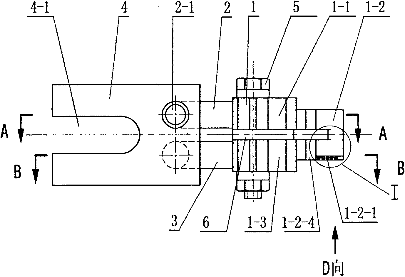
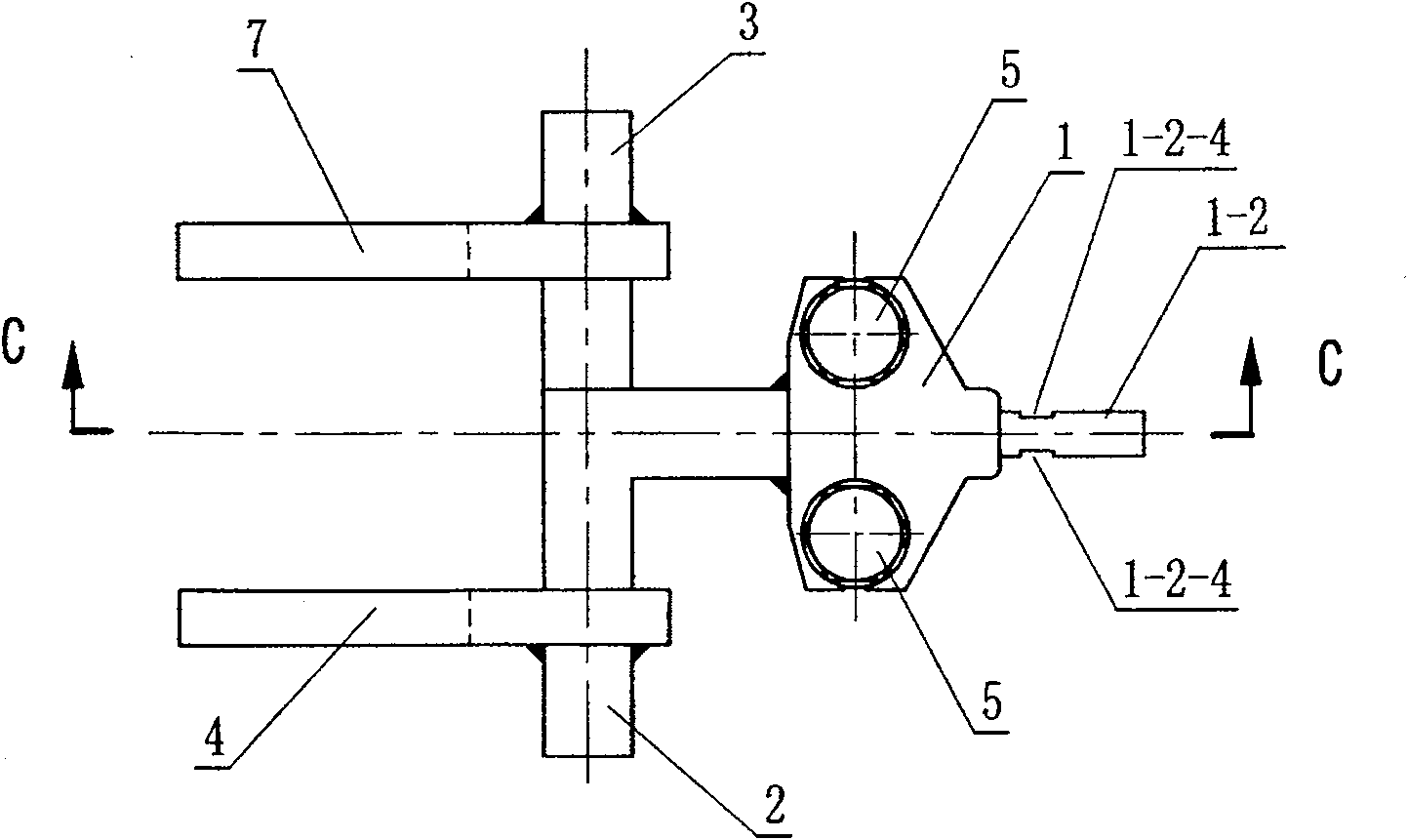
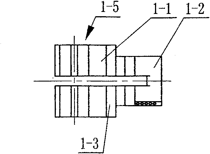
[0031] like figure 1 , 2 , 5, 6, 7, and 8, the piston ring groove quenching inductor of the present invention includes an induction head 1, a first connecting water pipe 2 and a second connecting water pipe 3, and the induction head 1 includes an upper wire 1-1, a lower Wire 1-3 and nose 1-2 with water channel 1-2-2, several water spray holes 1-2-1 are opened in the lower part of nose 1-2, the upper wire connecting water pipe 2 and sensor head 1 first 1-1 welding, the first connecting water pipe 2 inlet 2-1 passes through the inner cavity of the upper wire 1-1, the water channel 1-2-2 and the water spray hole 1-2-1, and the second connecting water pipe 3 and the induction head 1 The lower wire 1-3 is welded, the second connection water pipe 3 inlet 3-1 passes through the inner cavity of the lower wire 1-3, the water channel 1-2-2 is connected with the water spray hole 1-2-1, the upper wire 1-1 and the lower wire Insulation material 6 is housed between 1-3, and upper conducto...


PUM


Abstract

The invention discloses a quenching sensor for piston ring groove, comprising an induction head, a first connecting water pipe and a second connecting water pipe. The induction head comprises an upper wire, a lower wire and a nose part with water channel. The lower part of the nose part is equipped with a plurality of blowholes. The first connecting water pipe is welded with the upper wire of the induction head, and the inlet of the first connecting water pipe is communicated with the blowhole via an inner cavity of the upper wire and the water channel. The second connecting water pipe is welded with the lower wire of the induction head, the inlet of the second connecting water pipe is communicated with the blowhole via an inner cavity of the lower wire and the water channel. An insulation material is positioned between the upper wire and the lower wire, and the upper wire, the lower wire and the insulation material are fixed via fasteners. The quenching sensor for piston ring groove has the advantages of the high rigidness, the simple and reasonable structure, the low fabrication cost, being favorable for quenching of ring grooves with different shapes, and being conveniently fabricate and the good heat radiation.

Description

technical field [0001] The invention relates to a high-frequency quenching induction device, in particular to an inductor for piston ring groove quenching. Background technique [0002] The wear resistance of the piston top ring groove determines the service life of the piston top. It is one of the effective ways to increase the wear resistance by choosing an appropriate surface strengthening method for the piston top ring groove to improve the hardness of the piston top ring groove. The existing surface strengthening methods for the piston top ring groove include: laser surface quenching, surface nitriding treatment, Surface chrome plating and high frequency induction hardening. High-frequency induction hardening is mainly used for high-frequency induction hardening of various types of piston ring grooves above 4mm (including the arc transition area in the ring groove). Chinese patent document CN2368855Y discloses an inductor for piston ring groove quenching, which is mad...

Claims


Application Information

Patent Timeline
Patent Type & Authority Patents(China)
IPC IPC(8): C21D1/42
CPCY02P10/25
Inventor 戴冬
Owner CRRC QISHUYAN INSTITUTE CO LTD
Learn More