Supercharge Your Innovation With Domain-Expert AI Agents!

Drop head assembly of droplet pill machine

A dripping pill machine and dripper technology, which is applied to special packaging objects, solid materials, packaging, etc., can solve the problems of restricting the adjustment of the diameter of the dripping pill, the unstable operation of the quantitative pump, and the irregular shape of the opening, etc., to achieve good consistency , The process of dropping pills is stable and reliable, and the effect of relieving inconvenience

Inactive Publication Date: 2009-11-18
HEBEI UNIV OF TECH
View PDF6 Cites 0 Cited by
  • Summary
  • Abstract
  • Description
  • Claims
  • Application Information

AI Technical Summary

Problems solved by technology

[0005] 1. The opening of the end of the silicone tube is used as the drip nozzle. Due to the irregular shape of the opening, the shape of the dripping pill is not good and the roundness is poor;
[0006] 2. It is necessary to determine the size of the dropping pill by changing different silicone tubes, but the diameter of the silicone tube is very small, which limits the adjustment of the diameter of the dropping pill;
[0007] 3. Due to the fast heat dissipation at the end of the silicone tube, the temperature will drop, which will easily lead to the blockage of the liquid medicine and the instability of the dropping pill process;
[0008] 4. When adding a drip nozzle to the existing dripping machine, it is necessary to add a silicone tube, but due to the structure of the quantitative pump, it is impossible to add more silicone tubes, which limits the number of drip nozzles;
[0009] 5. In order to ensure that the dripping pills are well formed, the quantitative pump needs to work at a very low speed, and the quantitative pump works extremely unstable at this low speed, which is far below the rated speed, resulting in uneven size of the dropping pills and poor product quality. it is good

Method used


Image

  • Drop head assembly of droplet pill machine
  • Drop head assembly of droplet pill machine
  • Drop head assembly of droplet pill machine

Examples


Embodiment Construction

[0024] Further describe the present invention below in conjunction with embodiment and accompanying drawing thereof, but it does not limit the claims of the present invention.

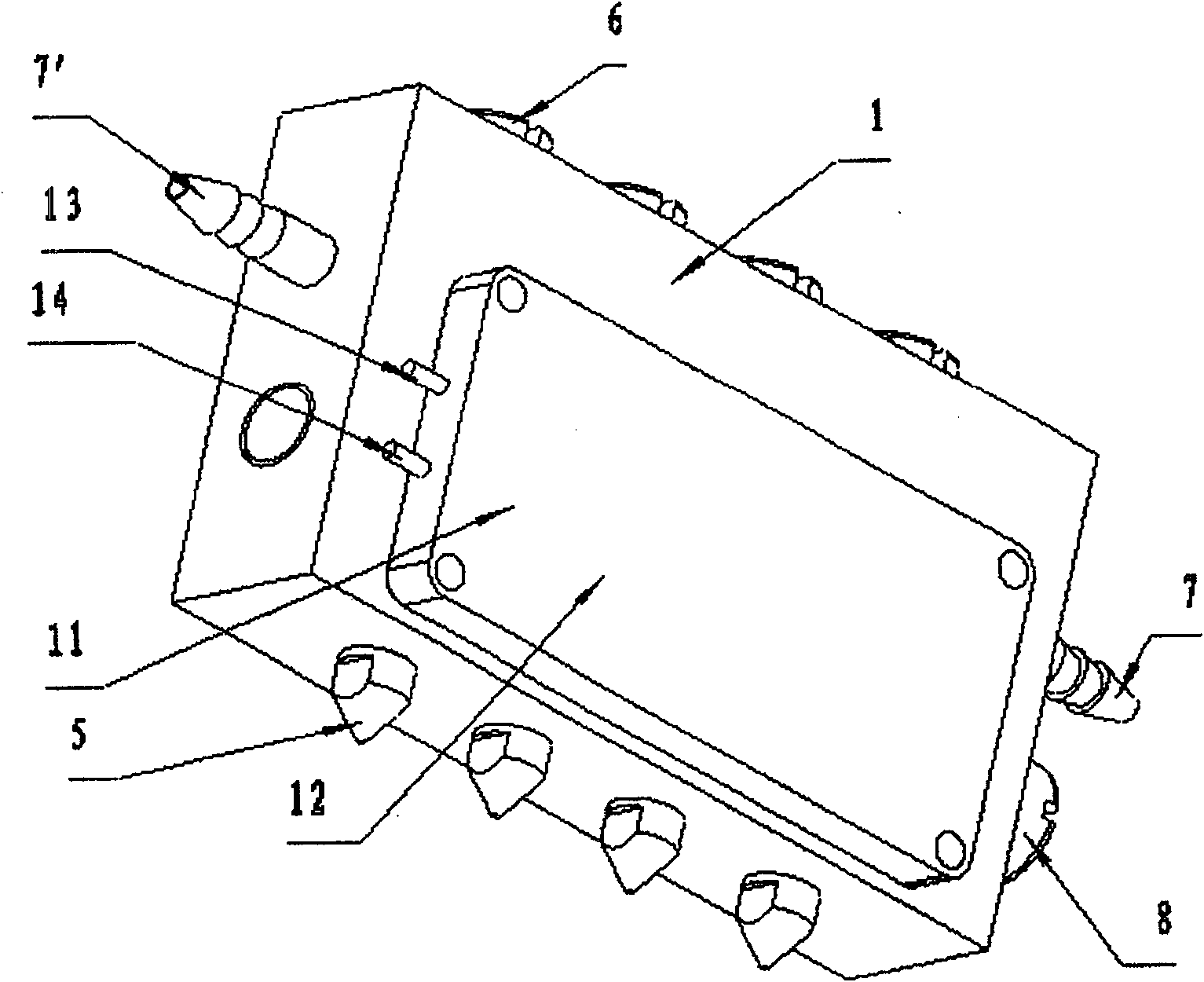
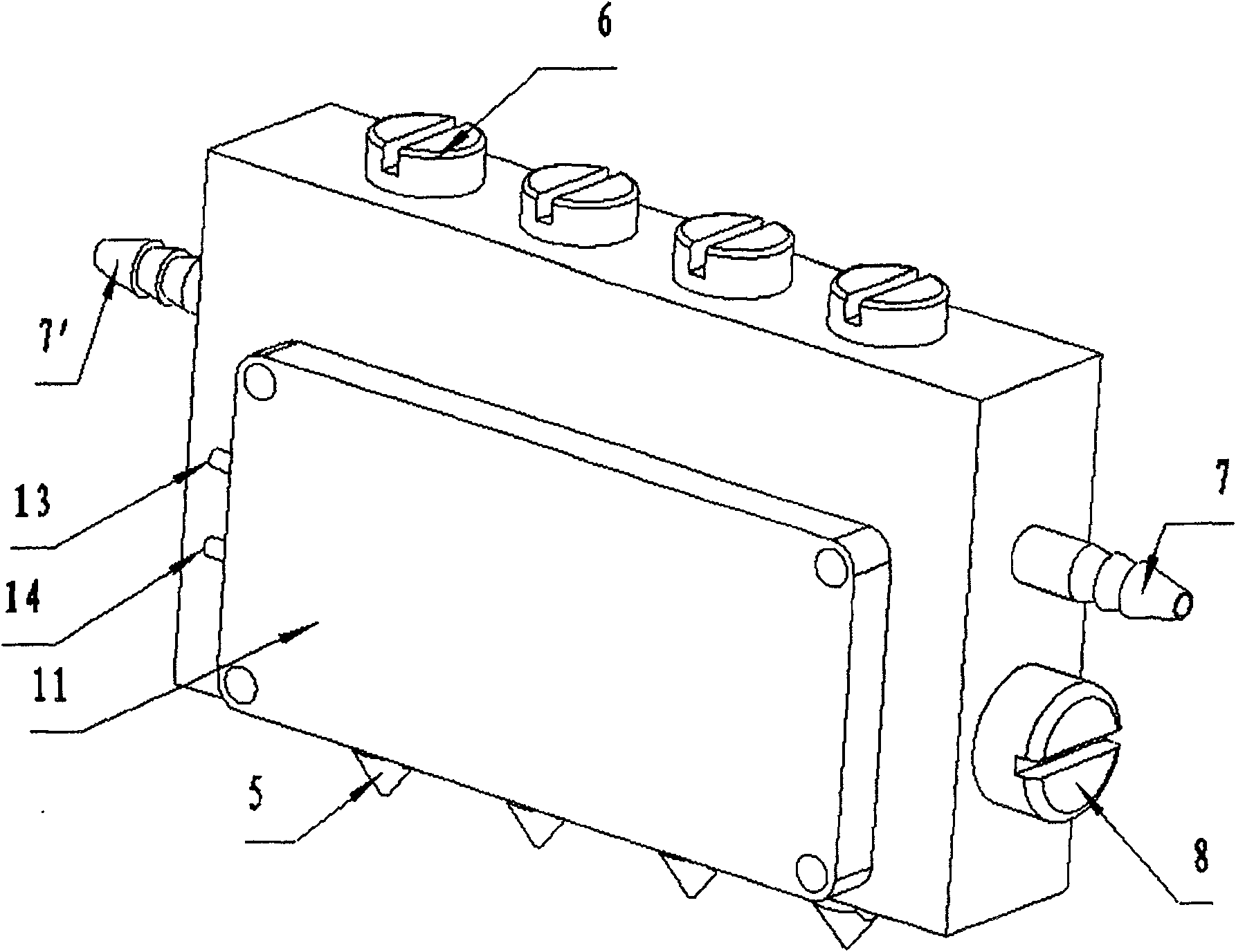
[0025] A kind of dropper assembly of dripping pill machine designed by the present invention (hereinafter referred to as dripper, see Figure 2-7 ), which is characterized in that it includes a housing 1, the housing 1 is punched with two or more through holes 2 parallel to each other for liquid communication, and each of the through holes 2 is covered by the first blind hole perpendicular to it 3 communicated, and a second blind hole 4 parallel to the first blind hole 3 is opened between the first blind hole 3 and the outlet of the housing at one end of each through hole 2; each through hole 2 The outlet of one end of the casing is equipped with a drip nozzle 5, and the outlet of the other end of the casing is equipped with a head 6; the opening of the casing of the first blind hole 2 is equipped with...


PUM


Abstract

The invention relates to a dripper assembly for a dripping pill machine, which is characterized in that it includes a housing, and the housing is punched with two or more through holes parallel to each other for liquid circulation, and each of the through holes is connected with it. The vertical first blind holes communicate, and a second blind hole parallel to the first blind hole is opened between the first blind hole and the outlet of the housing at one end of each through hole; each through hole The outlet of one end of the casing is equipped with a drip nozzle, and the outlet of the other end of the casing is equipped with a head; the opening of the casing of the first blind hole is equipped with a liquid pipeline interface; A throttle valve is matched in the blind hole, and the valve stem of the throttle valve is provided with holes that match the through-holes, and the through-holes on both sides can be completely communicated by rotating the throttle valve stem. , partially connected or completely blocked regulatory pores. The dripper assembly is convenient for mass production and efficiency improvement, and at the same time is beneficial for improving product quality and maintenance.

Description

technical field [0001] The present invention relates to the dripping head technology of the dropping pill machine in the field of pharmaceutical machinery, specifically a dripping head assembly of the dropping pill machine with a built-in heating device, adjustable flow rate and branch channel structure. The international patent classification number is proposed to be Int.Cl B65B 1 / 30 (2006.01). Background technique [0002] In recent years, with the continuous development of traditional Chinese medicine formulations, the application of dripping pills in traditional Chinese medicine formulations has become more and more eye-catching, and has been welcomed by patients and medical staff. It has broad prospects and huge potential to promote Chinese herbal medicines to the international market. market. The dripping pill machine is a manufacturing equipment for traditional Chinese medicine dripping pills. With the development of liquid medicine drop pill technology, the liquid ...

Claims


Application Information

Patent Timeline
Patent Type & Authority Patents(China)
IPC IPC(8): A61J3/06B65B1/30
Inventor 孙建广檀润华李志建曹国忠高金雍
Owner HEBEI UNIV OF TECH
Features
  • R&D
  • Intellectual Property
  • Life Sciences
  • Materials
  • Tech Scout
  • Unparalleled Data Quality
  • Higher Quality Content
  • 60% Fewer Hallucinations
Learn More