Switching regulator

A technology of switching regulators and comparators, which is applied in the direction of adjusting electrical variables, control/regulation systems, instruments, etc., and can solve problems such as incapable of IC

Inactive Publication Date: 2009-11-18
ROHM CO LTD
View PDF5 Cites 2 Cited by
  • Summary
  • Abstract
  • Description
  • Claims
  • Application Information

AI Technical Summary

Problems solved by technology

[0017] In the former soft-start circuit using a CR time constant circuit, as described in the prior art of Patent Document 1, the capacitor for the time constant becomes larger, and there is a problem that IC cannot be implemented.

Method used


Image

  • Switching regulator
  • Switching regulator
  • Switching regulator

Examples


Embodiment

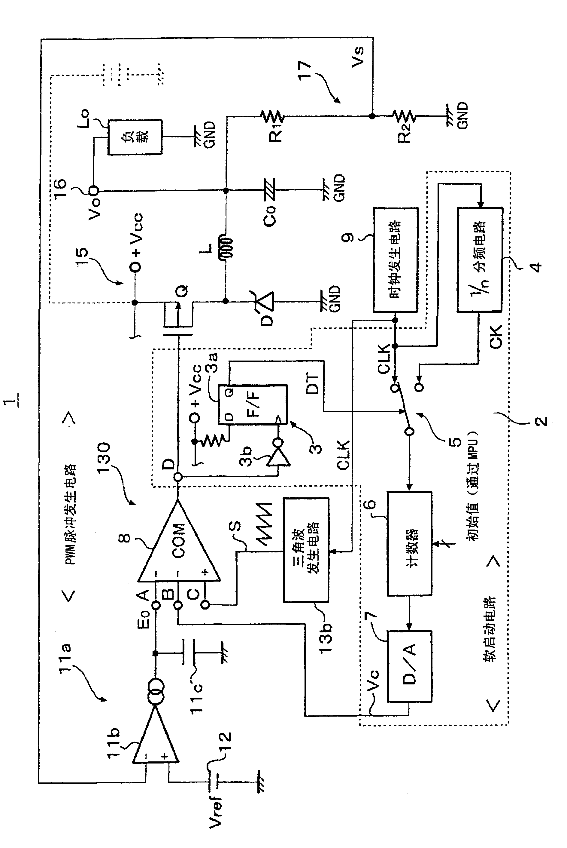
[0042] exist figure 1 of switching regulator 1, replacing the Figure 4 The soft start circuit 18 is provided with the soft start circuit 2.

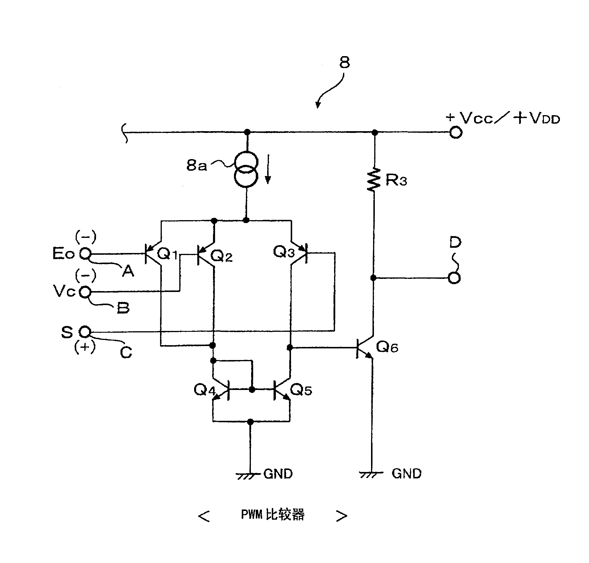
[0043] 130 is a PWM pulse generating circuit, which is composed of a soft start circuit 2, a PWM comparator 8, and a triangular wave generating circuit 13b.

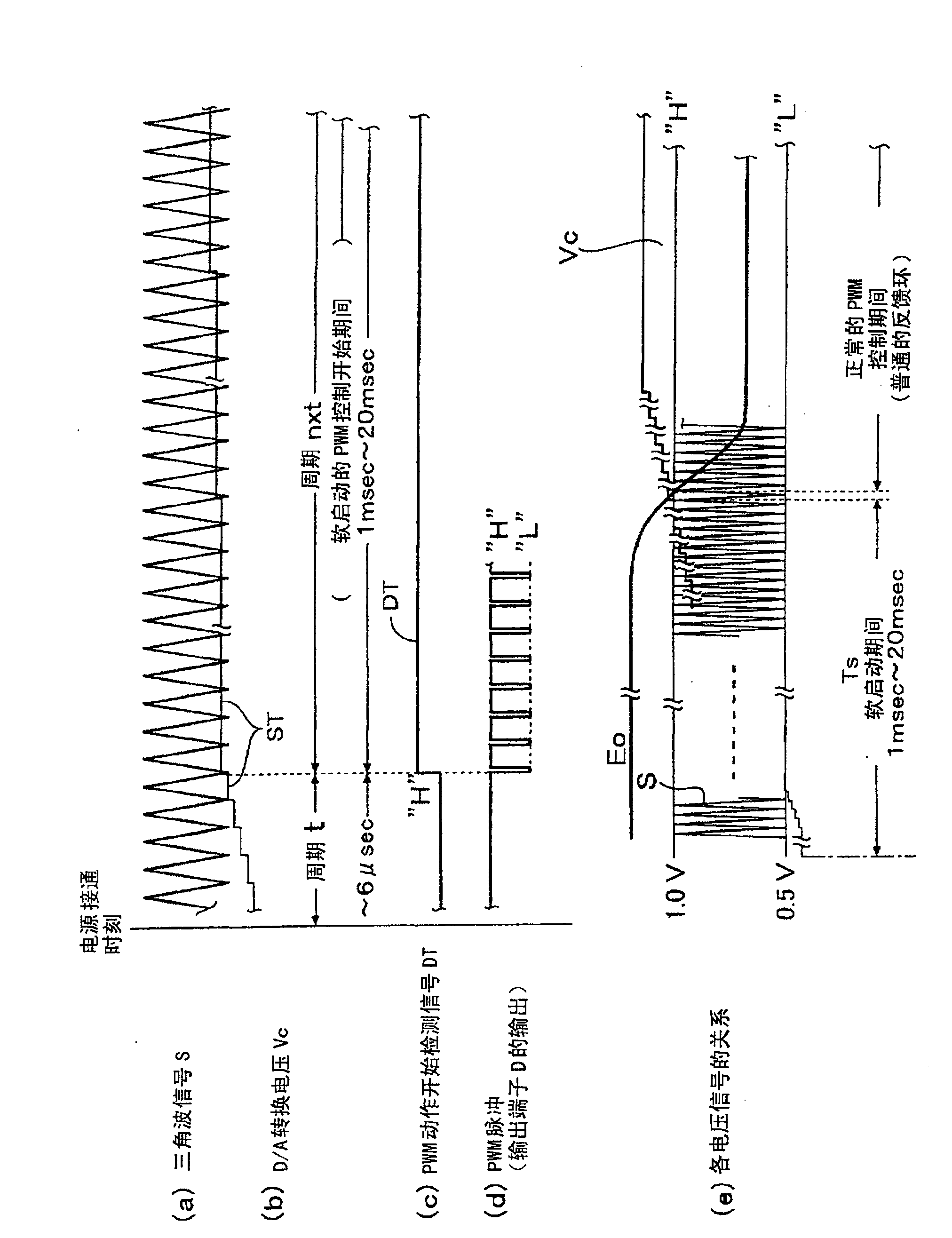
[0044] The soft start circuit 2 generates a step voltage signal ST (refer to image 3 (a)), the step voltage signal ST generates short-period and long-period step voltages. The soft start circuit 2 is composed of a PWM control start detection circuit 3, a 1 / n frequency division circuit 4, a selector 5, a counter 6, and a D / A conversion circuit (D / A) 7. The 1 / n frequency division circuit divides the clock CK by 4 and the clock CLK before frequency division. exist figure 1 middle, Figure 4 The drive 14 is removed, but the drive 14 can also be set.

[0045] The selector 5 controls the output of the start detection circuit 3 according to PWM, and switches the terminal selectio...


PUM


Abstract

The present invention provides a switching regulator which does not require a large time constant capacitor as a soft-start circuit, can reduce variation in soft-start time, shortens the time until power supply voltage stabilization control starts, and is suitable for IC. In the present invention, the output voltage of the soft start circuit is used as a step voltage signal that rises or falls at a predetermined rate, and the cycle of the step voltage change is set to a predetermined cycle when the power is turned on, and The output of the PWM pulse is monitored by the detection circuit, and the output signal of the soft start circuit is output according to the timing of changing from "H" to "L" or from "L" to "H" after the initial stage of the power-on. The change period of the step voltage is set to be greater than the prescribed period.

Description

technical field [0001] The present invention relates to a switching regulator (switching regulator), in particular to a DC / DC converter using a switching regulator, which is adapted to eliminate the need for a capacitor for obtaining a large time constant provided as a soft start circuit, and can reduce the This is an IC-based switching regulator that reduces the variation in soft-start time and shortens the time until power supply voltage stabilization control starts. Background technique [0002] Conventionally, in portable audio equipment, personal computers, PHS, mobile phones, and portable electronic equipment, in order to obtain efficiently converted power supply voltages, power supply circuits using DC / DC converters using switching regulators have been used. [0003] Figure 4 It is an explanatory diagram of an example of the DC / DC converter (switching regulator). [0004] 10 is a switching regulator, 11 is its error amplifier, 12 is a reference voltage generating ci...

Claims


Application Information

Patent Timeline
Patent Type & Authority Patents(China)
IPC IPC(8): H02M3/155
CPCH02M1/36H02M3/157Y10S323/901
Inventor 冈本成弘山伦章
Owner ROHM CO LTD
Why Eureka
Try Eureka