Rotating speed following system and method based on frequency conversion

A speed synchronization and converter technology, which is applied in the control system, electronic commutation motor control, multiple motor speed/torque control, etc., can solve the problem that the speed cannot be adjusted, and achieve low controller cost, reduced operation, and equipment simple effect

Inactive Publication Date: 2019-11-19
GUANGXI UNIV FOR NATITIES
View PDF4 Cites 0 Cited by
  • Summary
  • Abstract
  • Description
  • Claims
  • Application Information

AI Technical Summary

Problems solved by technology

[0003] The purpose of the present invention is to overcome the above problems and provide a closed-loop follow-up speed synchronization devi

Method used


Image

  • Rotating speed following system and method based on frequency conversion

Examples


Embodiment Construction

[0019] In order to make the objectives, technical solutions and effects of the present invention clearer and clearer, the present invention will be further described in detail below with reference to the accompanying drawings and examples. It should be understood that the specific embodiments described herein are only used to explain the present invention, but not to limit the present invention.

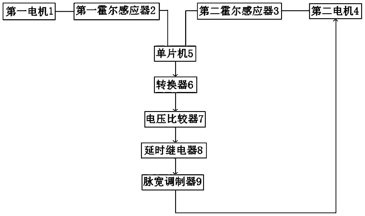
[0020] like figure 1 As shown, a closed-loop following rotational speed synchronization device and system described in this embodiment includes a motor, a Hall sensor, a single-chip microcomputer 5 , a converter, a voltage comparator 7 , a delay relay 8 and a pulse width modulator 9 .

[0021] The motor includes a first motor 1 and a second motor 4. The end of the rotating shaft of the first motor 1 is provided with a driving wheel, and the end of the rotating shaft of the second motor 4 is provided with a driven wheel. The rotational speed is converted into a pulse signal, the Hall...


PUM


Abstract

The invention relates to the technical field of electronic circuits, and particularly discloses a closed-loop following rotating speed synchronization device and system. The device comprises a motor,a Hall sensor, a single-chip microcomputer, a converter, a voltage comparator, a time-delay relay, and a pulse width modulator. The Hall sensor is arranged on a rotating shaft of the motor; the outputend of the Hall sensor is connected with the input pin of the single-chip microcomputer. The output pin of the single-chip microcomputer is connected with the input end of the converter. The output end of the converter is connected to the input end of the voltage comparator, the output end of the voltage comparator is connected to the input end of the time delay relay, the output end of the timedelay relay is connected to the input end of the pulse width modulator, and the output end of the pulse width modulator is connected to the voltage input end of the motor. The system is simple in useddevices and low in controller cost, a driven wheel can dynamically change along with the rotating speed of the driving wheel, the rotating speed does not need to be manually set, and therefore, brakeoperation is reduced.

Description

【Technical field】 [0001] The present invention relates to the technical field of electronic circuits, in particular to a system and method for speed following based on frequency conversion. 【Background technique】 [0002] The current speed following method is mainly based on manually setting the speed and cannot be dynamically adjusted. Therefore, it is particularly difficult to adjust the speed when the speed changes at any time. The application number is: CN201811209033.1 A motor speed adjustment circuit and device, through a simple circuit structure, can measure the motor speed in real time, read the power supply voltage of the motor intuitively, and adjust the motor speed by adjusting the power supply voltage, The closed-loop adjustment of the motor speed adjustment is realized, and the accuracy of the motor speed adjustment is ensured. This technology can only be used to manually set the speed and cannot be applied to a dynamic environment. [Content of the invention] ...

Claims


Application Information

Patent Timeline
IPC IPC(8): H02P6/00H02P6/04
CPCH02P6/00H02P6/04
Inventor 文春明李尚平周永权文国富李大庆蒋荣萍廖义奎黄天星赵迎新冯冰王永李猛关明海陈敏博韦尚豪陈晓锋姚玉权陈昌毅曾璐黄寿彰曹旭光卢玉春
Owner GUANGXI UNIV FOR NATITIES
Why Eureka
Try Eureka