Cavity filter test system and method

A cavity filter and test system technology, applied in the electronic field, can solve problems such as difficult time determination, difficult control error, and increased test difficulty, and achieve the effects of increased convenience of use, fast air pressure balance, and improved test efficiency

Inactive Publication Date: 2009-11-25
HUAWEI TECH CO LTD
View PDF2 Cites 0 Cited by
  • Summary
  • Abstract
  • Description
  • Claims
  • Application Information

AI Technical Summary

Problems solved by technology

[0005] 1. The low-pressure trial box 2 is manufactured by a specialized manufacturer, with large volume, high power consumption, high noise and high manufacturing cost;
[0006] 2. Due to the large volume and poor mobility of the low-pressure test chamber 2, it is difficult to be placed in the production line and flexibly applied, and the usability is poor
[0007] 3. The component to be tested 1 is placed in the low air pressure test chamber 2, and the air pressure in the cavity must be balanced. The balance time is related to the airtightness of the component to be tested 1. This time is difficult to determine, and it is difficult to control according to empirical values. error
[0008] 4. Due to the fixed internal space of the low-pressure test chamber 2, it cannot be used for components to be tested 1 whose volume is larger than the internal operating space of the low-pressure test chamber 2.
[0009] 5. The component to be tested 1 is placed in the low-pressure test box 2. It is extremely inconvenient to test the connecting wire, and the longer connecting wire and too many transfers will cause the change of the test index, increase the attenuation, and make the test more difficult , the test uncertainty increases

Method used


Image

  • Cavity filter test system and method
  • Cavity filter test system and method
  • Cavity filter test system and method

Examples


Embodiment 1

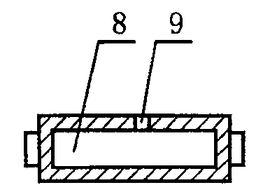
[0035] Such as figure 2 As shown, the cavity of the cavity filter is provided with vent holes 9 for communicating the inner cavity 8 with the outside world. The vent hole 9 is set on the device cavity of the cavity filter, and can be set on each surface, and can even be set at the device pin of the cavity filter, as long as the air can be extracted in the follow-up work Just belong to the scope of the present invention.

Embodiment 2

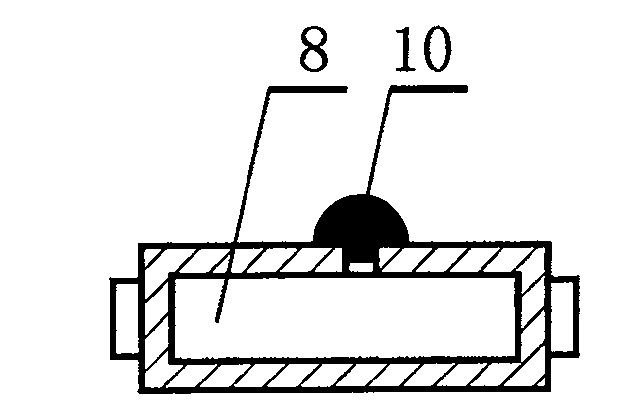
[0037] Such as image 3 As shown, on the basis of the first embodiment, the air hole 9 is also provided with a sealing plug 10 for the purpose of realizing the airtightness of the cavity filter itself after the test is completed. Normally, the sealing plug 10 can be realized with paraffin wax, sealant such as silica gel, wax, etc. Of course, for the standardization of production, the sealing plug 10 can also be an independent component made of sealing materials such as rubber.

[0038] At the same time, there is at least one vent hole 9, that is to say, in order to reach the required target value more quickly, a plurality of vent holes 9 can be provided at the same time.

Embodiment 3

[0040] Such as Figure 4 As shown, on the basis of Embodiment 1 or Embodiment 2, an interface 11 may also be provided at the ventilation hole 9, and the interface 11 is used to connect a ventilation pipeline 12.

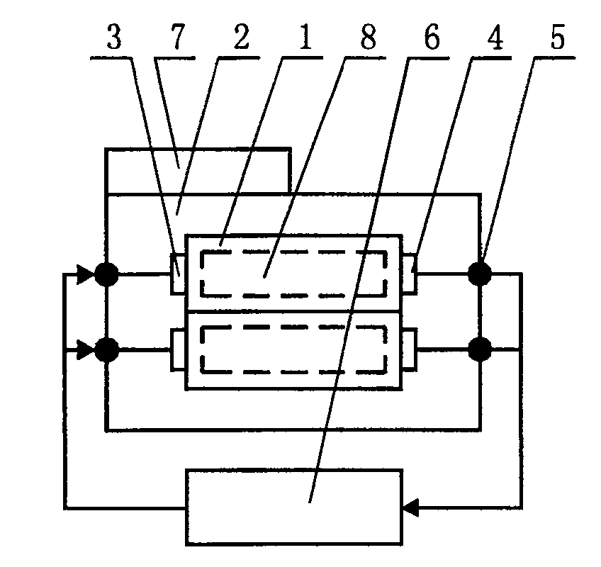
[0041] A cavity filter testing system according to the present invention is used for testing the above-mentioned cavity filter, and its specific implementation is as follows:


PUM


Abstract

The invention provides a cavity filter and its testing system and method. A vent hole is provided in the cavity filter to connect the cavity with the outside world. The test system includes a test device, a low-voltage measurement and control device and an air source device. The input port and output port of the cavity filter are connected to the test device; the low-voltage measurement and control device and the gas source equipment The source device is connected to the vent hole of the cavity filter, and the pressure of the inner cavity of the control cavity filter is in the low-pressure test area. The cost is reduced, the occupied space is reduced, the power consumption is reduced, and the convenience of use is increased. Small size, good maneuverability, easy to add to the production line. The air pressure balance is fast and the test efficiency is improved. It can satisfy components (1) to be tested in different shapes and sizes, without volume limitation. If it is used with a high and low temperature humid heat box, the component to be tested (1) is placed in the high and low temperature humid heat box, and the air source device (15) is connected to the component to be tested (1) through a gas pipe, so that high and low temperature humid heat and low air pressure can be performed. The characteristic test of the component under test (1) under the condition.

Description

technical field [0001] The invention relates to the field of electronic technology, in particular to a cavity filter testing system and method. Background technique [0002] Cavity filters are widely used in the field of electronic technology. For example, in the radio frequency front-end of equipment such as wireless base stations or repeaters, they are generally equipped with cavity filters (such as duplexers) with air as the medium. The RF signal is filtered and duplexed. When the atmospheric pressure in the area where the cavity filter is used is different, the power capacity of the cavity filter with air as the medium changes with the change of air pressure. When the external atmospheric pressure decreases, the power capacity of the cavity filter also decreases ; Conversely, when the external atmospheric pressure increases, the power capacity of the cavity filter also increases; therefore, for base stations at high altitudes, due to the low external atmospheric pressur...

Claims


Application Information

Patent Timeline
Patent Type & Authority Patents(China)
IPC IPC(8): H01P1/207G01R31/00
Inventor 刘选鹏
Owner HUAWEI TECH CO LTD
Why Eureka
Try Eureka