PWM rectifying system based on IGCT and its working method

A rectification system, the said technology, is applied in the direction of output power conversion device, AC power input conversion to DC power output, electrical components, etc., which can solve the problem of power device current carrying, small voltage withstand capacity, and unsuitable rectification system for large power grids. , AC side power factor drop and other issues, to achieve the effect of improving current carrying capacity, easy to understand software programming, and improving power factor

Inactive Publication Date: 2009-12-16
TIANJIN UNIVERSITY OF TECHNOLOGY
View PDF3 Cites 0 Cited by
  • Summary
  • Abstract
  • Description
  • Claims
  • Application Information

AI Technical Summary

Problems solved by technology

[0002] The electric power industry is a pillar industry of the national economy, and the power conversion system is widely used in the power system. The power conversion system includes: rectification (AC to DC) system, inverter system (DC to AC), etc. The PWM rectification system based on IGCT can Effectively reduce the harmonic content after rectification, significantly improve the power factor of the AC side, and realize the rapid adjustment of the rectification system. The rectification systems that have been studied so far include static semiconductor rectification systems and static ion rectification systems. These systems have their own advantages and disadvantages. Advantages and disadvantages, the main problem is to reduce the power factor of the AC side and cause pollution to the public power grid. At the same time, the power device used in it has a small current-carrying and voltage withstand capacity, which is not suitable for the rectification system of the large power grid. Therefore, the development of public The PWM rectifier with no pollution to the power grid and high-efficiency power quality is still an important research direction

Method used


Image

  • PWM rectifying system based on IGCT and its working method
  • PWM rectifying system based on IGCT and its working method
  • PWM rectifying system based on IGCT and its working method

Examples


Embodiment Construction

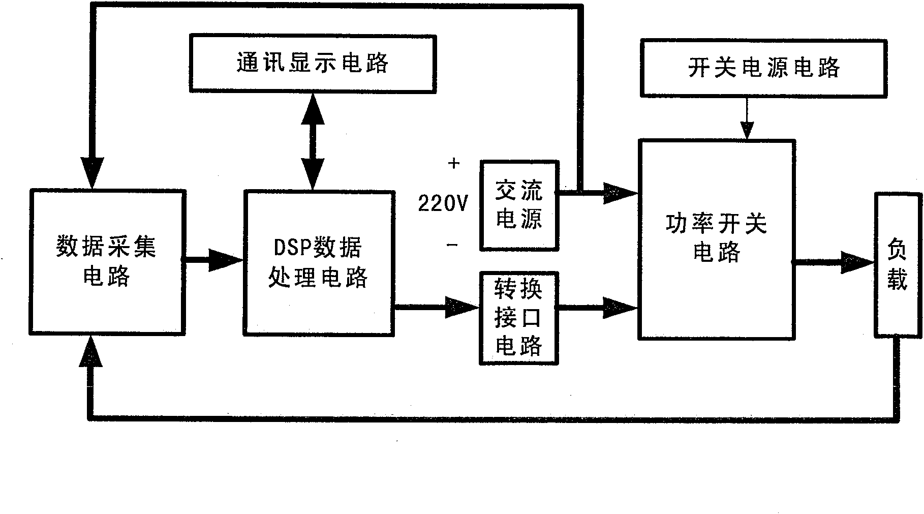
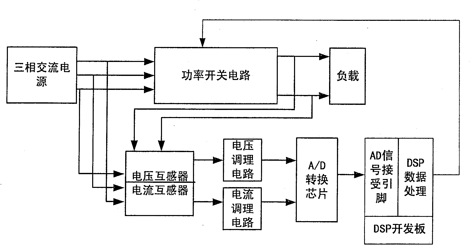
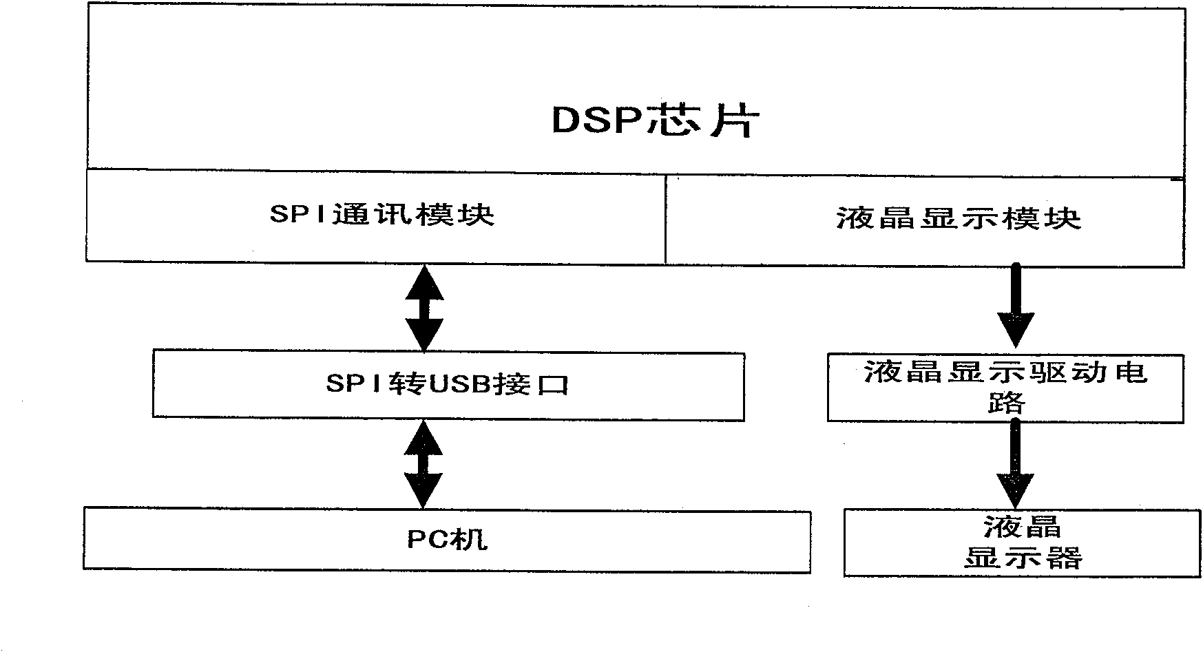
[0024] A PWM rectification system based on the IGCT of GVC733CE is characterized in that it comprises a data acquisition circuit, a TMS320F2812 DSP data processing circuit, a conversion interface circuit, a power switch circuit, a switching power supply circuit and a communication display circuit (see figure 1 ); said data acquisition circuit input end is connected to the AC power supply of load end and 220V respectively, its output end is connected to the input end of DSP data processing circuit, and the output end of TMS320F2812DSP data processing circuit is connected to the input end of conversion interface circuit; The output end of the conversion interface circuit is connected to the input end of the power switch circuit, the switching power supply circuit supplies power to the power switch circuit, and the output end is connected to the power input end of the power switch circuit; the input end of the communication display circuit is connected to To the corresponding outp...


PUM


Abstract

An IGCT-based PWM rectification system is characterized in that it consists of a data acquisition circuit, a DSP data processing circuit, a conversion interface circuit, a power switch circuit, a switching power supply circuit and a communication display circuit. Its advantages are: the hardware system is combined with computer software programming, the hardware design is simple, and the software programming is easy to understand; the three-phase phase voltage and phase current of the AC side are collected, and the power factor of the grid side is improved through the SVPWM algorithm without causing pollution to the grid. Green rectification system; IGCT is used as the switching device of the power circuit. Compared with IGBT and GTO, the current carrying capacity and withstand voltage capacity of the switching device are improved; the conversion interface circuit from PWM electrical signal to PWM optical signal is designed to ensure the IGCT Reliable turn-on and turn-off; using DSP data processing capabilities, it can perform fault detection and automatic error correction functions to improve system reliability.

Description

(1) Technical field: [0001] The invention belongs to the field of power system rectification control, in particular to an IGCT (integrated gate commutated thyristor)-based PWM (pulse width modulation) rectification system and its working method, which integrates hardware technology and software programming. (two) background technology: [0002] The electric power industry is a pillar industry of the national economy. The electric energy conversion system is widely used in the electric power system. The electric energy conversion system includes: rectification (AC to DC) system, inverter system (DC to AC), etc. The PWM rectification system based on IGCT can Effectively reduce the harmonic content after rectification, significantly improve the power factor of the AC side, and realize the rapid adjustment of the rectification system. The rectification systems that have been studied so far include static semiconductor rectification systems and static ion rectification systems. Th...

Claims


Application Information

Patent Timeline
Patent Type & Authority Patents(China)
IPC IPC(8): H02M7/162H02M7/527
Inventor 马幼捷邵宝福周雪松吴平安张跃均康文广安小东丰美丽
Owner TIANJIN UNIVERSITY OF TECHNOLOGY
Why Eureka
Try Eureka