Brake device for a vehicle with an electric parking brake system and corresponding control method

A technology of braking equipment and braking devices, applied in the direction of braking control systems, manual starting devices, automatic starting devices, etc., can solve the problems of unrealizable braking effect, insufficient deceleration, etc., and achieve load reduction and loss reduction Effect

Active Publication Date: 2009-12-23
CONTINENTAL AUTOMOTIVE SYST SHANGHAI
View PDF8 Cites 2 Cited by
  • Summary
  • Abstract
  • Description
  • Claims
  • Application Information

AI Technical Summary

Problems solved by technology

This can lead to the vehicle starting to roll undesirably (Anrollen) or to insufficient deceleration
[0007] In addition, during braking controlled by the driver there is the danger that the desired braking effect cannot be achieved due to faults in the brake system

Method used


Image

  • Brake device for a vehicle with an electric parking brake system and corresponding control method

Examples


Embodiment Construction

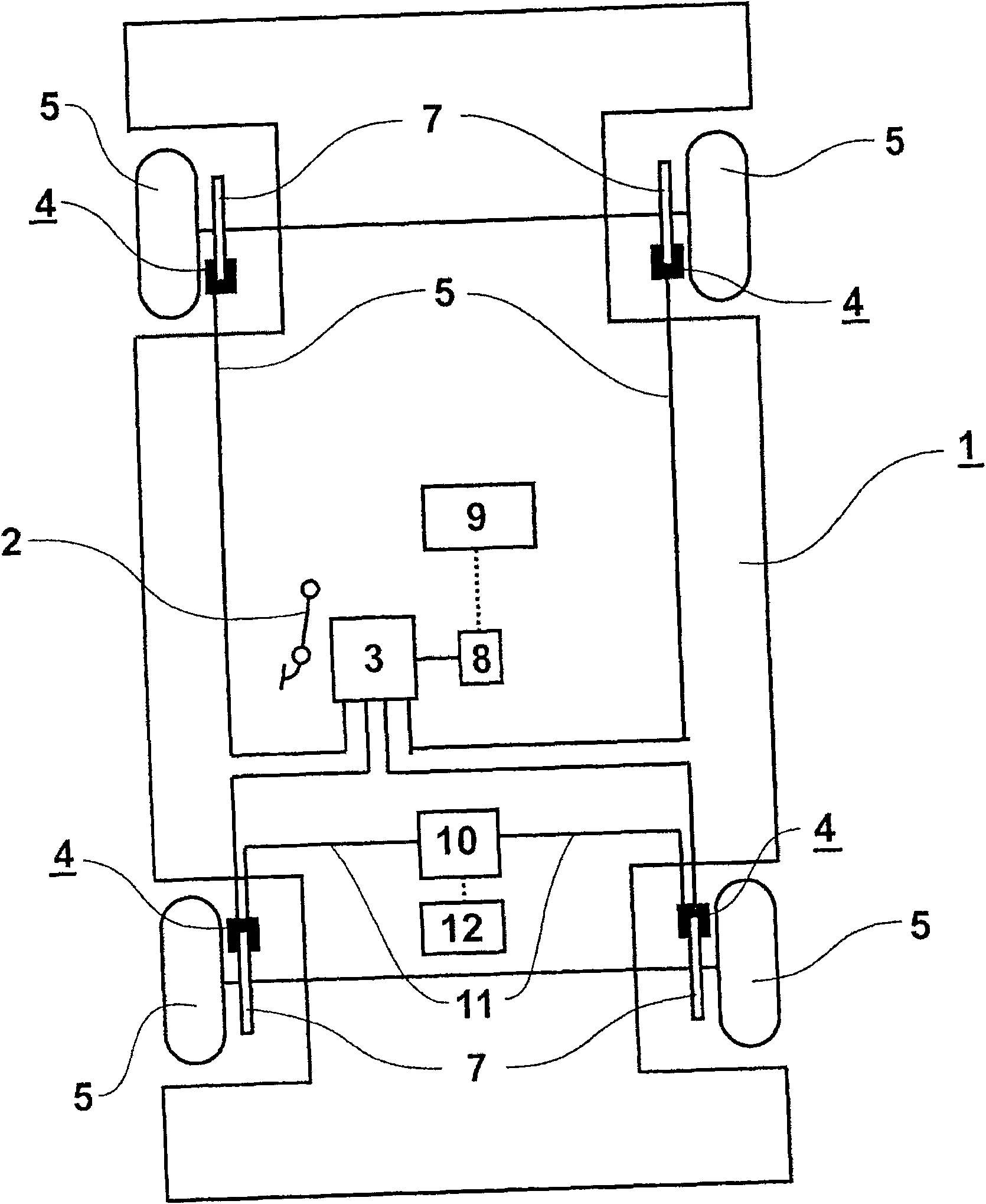
[0032] figure 1 The brake system shown in includes a hydraulic service brake system of a vehicle 1 with an operating device 2, a master cylinder 3 and wheel brakes 4 on the respective brake wheels 5 of the vehicle 1 with wheel brakes The wheel brake cylinder is fluidly connected to the main brake cylinder 3 via a brake line 6 .

[0033] The operating device 2 is usually designed as a brake pedal which is actuated by the driver of the vehicle 1 . When pressure is applied to the brake pedal, a pressure is built up by the driver inside the brake fluid in the master cylinder 3, which is transmitted to the wheel brakes 4 via the brake lines 6, whereby, in the wheel brakes 4, the The brake pads on the piston are pressed against the brake disc 7 .

[0034] The service brake system can be a conventional mechanical brake system in which the force exerted by the driver when actuating the actuating device 2 is amplified by a brake booster in order to build up brake pressure within the ...


PUM


Abstract

The invention relates to a brake system for a vehicle, comprising a hydraulic service brake device with an energy supply unit, which builds up a brake pressure according to a pressure requirement inside a master brake cylinder of the service brake device, which Brake pressure is transmitted to at least one wheel brake, and the brake system also includes an electric parking brake. According to the invention, the brake system is characterized in that, during operation of the service brake system, a control unit compares the pressure demand with the brake pressure in at least one wheel brake and / or by comparing the detected vehicle acceleration with the The expected vehicle acceleration according to the pressure is used to check whether there is a fault in the service brake; when it is determined that a fault has occurred, the control unit activates the electric parking brake. Furthermore, the invention relates to a method for controlling a braking system of a vehicle.

Description

technical field [0001] The invention relates to a braking system for a vehicle comprising a hydraulic service brake system with an energy supply unit which establishes a braking system according to the pressure requirements inside the master brake cylinder of the service brake system. Dynamic pressure, the brake pressure is transmitted to at least one wheel brake, the brake system also includes an electric parking brake device. [0002] Furthermore, the invention relates to a method for controlling a brake system of a vehicle, wherein a brake pressure is built up in a master brake cylinder of a hydraulic service brake system according to a pressure requirement and is transmitted to at least one wheel brakes. Background technique [0003] Motor vehicles are usually equipped with hydraulic service brake systems, in which brake pressure is built up inside the hydraulic medium in the master cylinder and transmitted to the brake cylinders of the wheel brakes, which are passed th...

Claims


Application Information

Patent Timeline
Patent Type & Authority Patents(China)
IPC IPC(8): B60T8/88B60T7/12B60T7/10B60T13/74B60T17/22F16D65/28
CPCB60T13/746B60T8/885B60T2270/402B60T17/221B60T7/107B60T2201/06B60T7/122B60T7/08B60T8/88B60T13/74B60T17/22
Inventor M·拜杰恩斯O·胡特M·奥利T·莫伊雷尔斯P·维舍
Owner CONTINENTAL AUTOMOTIVE SYST SHANGHAI
Why Eureka
Try Eureka