
Composite shuttle for loom and production thereof

A manufacturing process and technology of looms, applied in textiles, shuttles, textiles and papermaking, etc., can solve problems such as large product deformation, brittle shuttles, and scrapped shuttles, and achieve anti-static service life, good wear resistance, and labor low intensity effect

Inactive Publication Date: 2009-12-23
郑州豫达机械制造有限公司
View PDF8 Cites 0 Cited by
  • Summary
  • Abstract
  • Description
  • Claims
  • Application Information

AI Technical Summary

Problems solved by technology

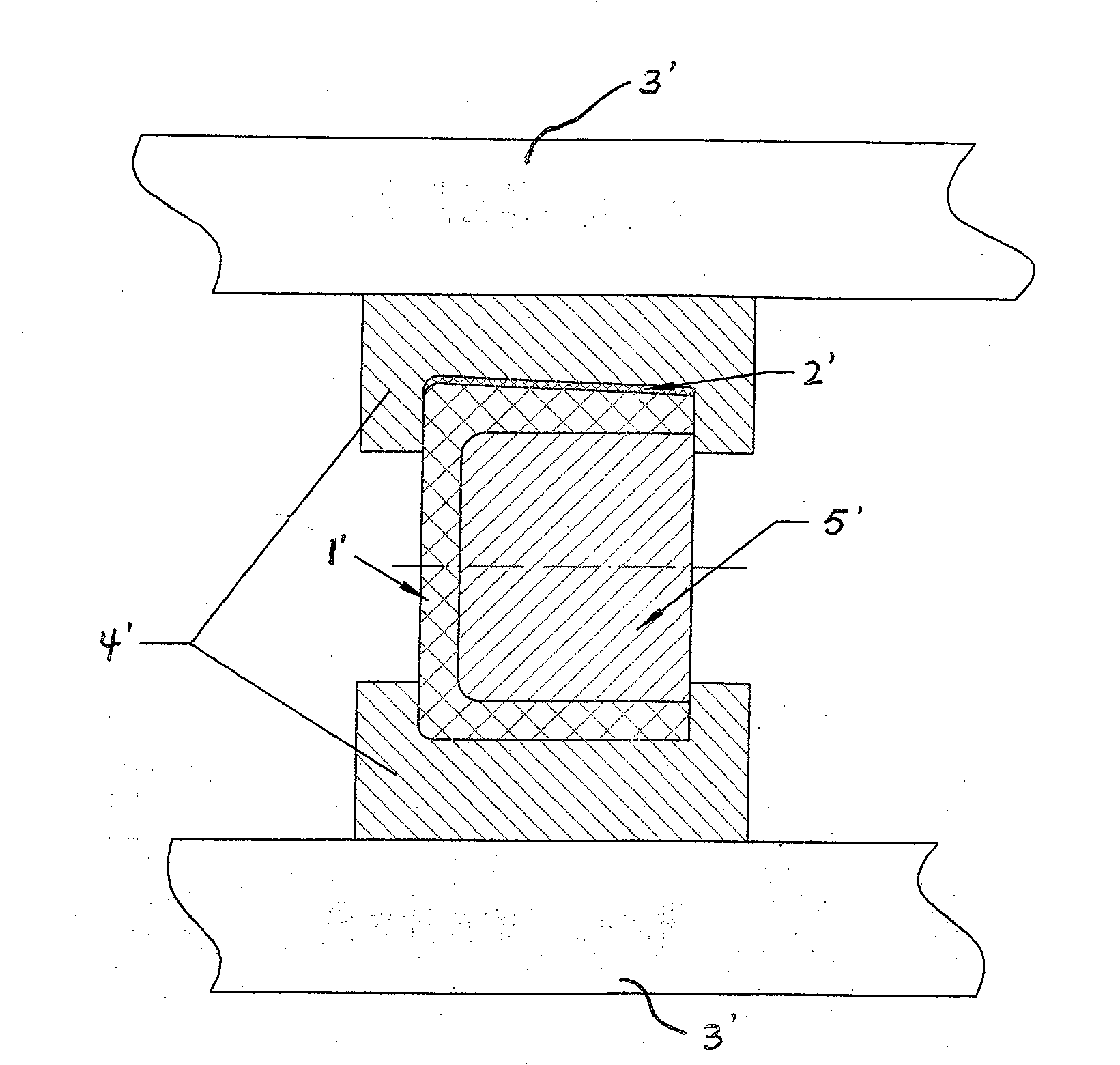
[0008] 6. During heat-covering, once heat-covering quality problems occur, for example, local sol is uneven, etc., the entire shuttle will be scrapped
[0010] 1. Due to the use of hydraulic presses and molds for production and processing, the investment is relatively large;
[0011] 2. Since high temperature and high pressure are used during production and processing, and the duration is long, the energy consumption is high;
[0012] 3. The whole process includes installation, temperature rise, pressure maintenance, cooling, disassembly, etc. There are many steps and long time, so the production efficiency is low;
[0013] 4. Due to the high temperature and high pressure processing, the product deformation is large;
[0014] 5. Since there is no reworkability and the process requirements are high, the production rate is low;
[0015] 6. The most important thing is that under the action of high temperature and high pressure, the original excellent toughness of the shuttle blank is seriously lost, and the shuttle is easily brittle

Method used


Image

  • Composite shuttle for loom and production thereof
  • Composite shuttle for loom and production thereof
  • Composite shuttle for loom and production thereof

Examples


Embodiment 1

[0040] The profile of composite shuttle of the present invention (as image 3 Shown) and the shuttle (such as figure 2 Shown) the appearance is basically the same, the difference lies in the way of production, the specific production process is as follows:

[0041] ①Use the shuttle molding die to process a shuttle blank 1 with a groove 3 on one side (such as Figure 4 , 5 Show);

[0042] ②According to the size of the mosaic groove on the side of the shuttle blank, the board to be compounded is punched out to match the shape of the groove, and the composite board (phenolic resin laminated cloth board or ultra-high molecular weight polyethylene and other high wear-resistant boards can be selected) board, antistatic board) the thickness of 1-2MM is appropriate;

[0043] ③ Using double-sided tape (double-sided cloth tape or double-sided foam tape), bond the composite board 2 to the groove 3 of the shuttle blank 1, and make all parts fully bonded;

[0044] ④ If the gap betwee...

Embodiment 2

[0047] The difference between this embodiment and Embodiment 1 is that grooves are processed on both sides of the shuttle blank (see Figure 4 ), the grooves on both sides of the shuttle blank are inlaid with composite boards, and the bonding glue is No. 0 bonding glue.

[0048] Adhesive glue can also select other currently known suitable normal-temperature adhesives.


PUM


Abstract

A composite shuttle for a loom and its manufacturing process. The composite shuttle consists of a shuttle blank body and a composite plate embedded in a pre-processed groove on the side of the shuttle blank body by bonding. That is, the composite shuttle is produced by the cold inlay bonding process. The characteristics of this new process are: normal temperature, inlaying, and bonding—the phenolic resin laminated cloth board or ultra-high molecular polyethylene and other high-wear-resistant plates, through the adhesive, Adhesive, glued to the surface of the shuttle at room temperature. The advantages of the present invention are: there is no need to pre-process the side of the shuttle blank, since the entire production process does not require a press and a large number of molds, so the investment is very small, and the production and processing are carried out under normal temperature and pressure, without heating and pressing, and without Machine processing, so there is no energy consumption, the labor intensity of workers is low, and the production efficiency is high; most importantly, because it is processed at room temperature, it has no effect on the original excellent toughness of the shuttle body. Static and long life.

Description

technical field [0001] The invention relates to a loom accessory of textile equipment, in particular to a composite shuttle for a loom and a manufacturing process thereof. Background technique [0002] The shuttle is an important accessory of the shuttle loom and plays an important role in sending weft. Due to the shortage of wood, people use plastic instead of wood to produce plastic shuttles, and the development is very fast. For further improving the wear resistance and antistatic properties of plastic shuttles, people have developed composite plastic shuttles again. At present, the production of this kind of composite plastic shuttle adopts the traditional heat-coating process, that is, the surface of the plastic shuttle is heat-coated with phenolic resin cloth through high temperature (160-180°C) and high pressure (3MPA) to improve the wear resistance. and antistatic properties. This heat-covering production process has low efficiency, high energy consumption, and la...

Claims


Application Information

Patent Timeline
Patent Type & Authority Patents(China)
IPC IPC(8): D03J5/02
Inventor 陈龙军宁玉明
Owner 郑州豫达机械制造有限公司
Learn More