Layered piezoelectric element and injection device using the same
A piezoelectric element, laminated technology, applied in the manufacture/assembly of fuel injection devices, piezoelectric/electrostrictive devices, electrical components, etc., can solve problems such as changes in displacement characteristics, to prevent the reduction of displacement characteristics, The effect of improving the bonding strength
- Summary
- Abstract
- Description
- Claims
- Application Information
AI Technical Summary
Problems solved by technology
Method used
Image

Examples
no. 1 Embodiment approach
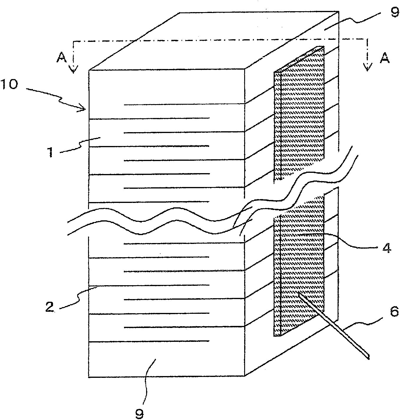
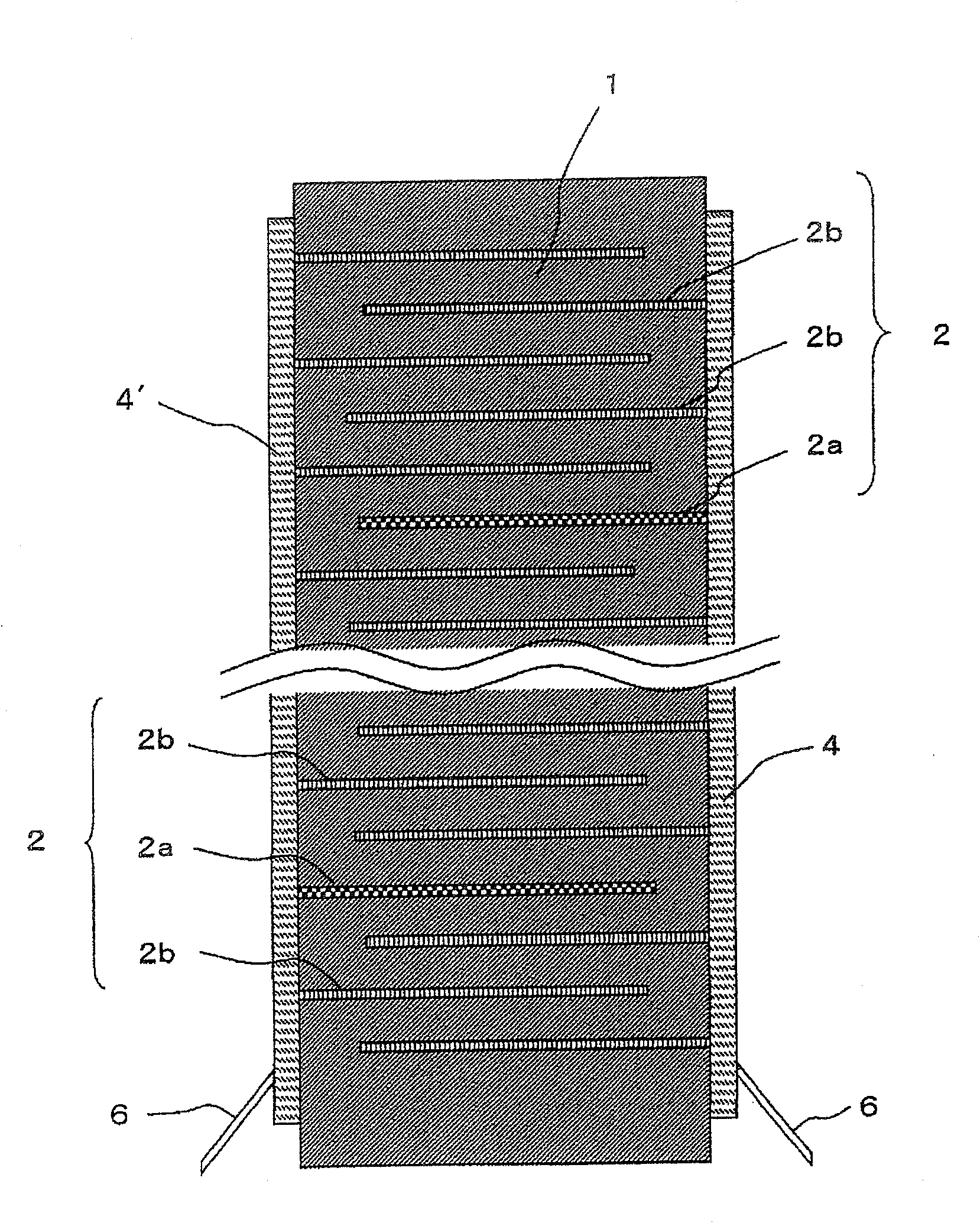
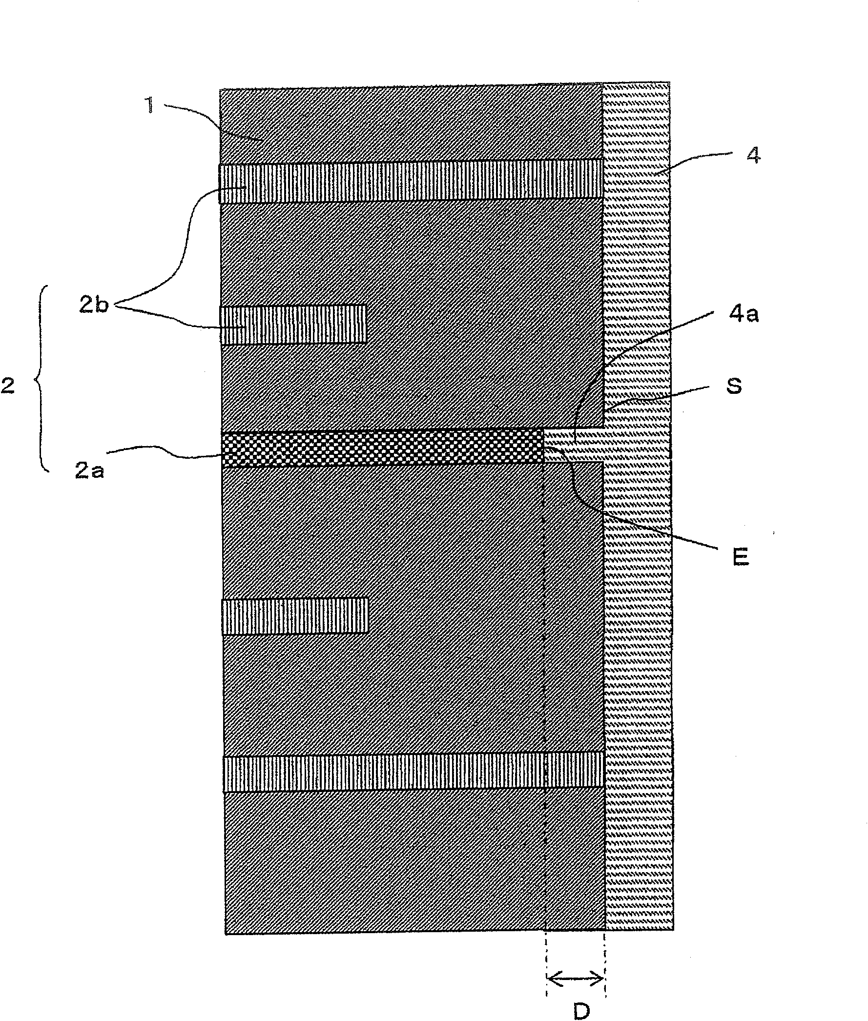
[0098] An embodiment of the present invention will be described in detail below with reference to the accompanying drawings. figure 1 It is a perspective view showing the multi-layer piezoelectric element related to the first embodiment of the present invention. figure 2 for figure 1 The A-A line profile in. image 3 It is an enlarged cross-sectional view of the joint portion between the external electrode 4 and the side surface of the laminated body 10 according to this embodiment.
[0099] like figure 1 and figure 2 As shown, the multi-layer piezoelectric element of this embodiment has a laminated body 10 in which a plurality of piezoelectric layers 1 and a plurality of metal layers 2 are alternately stacked, and each of the A pair of external electrodes (covering members) 4, 4' are electrically connected to the end of the metal layer 2 via an alternate layer. Lead wires 6 are respectively fixed to the external electrodes 4, 4' by solder or the like. These lead wi...
no. 2 Embodiment approach
[0121] Figure 4 It is a cross-sectional view showing a related multi-layer piezoelectric element according to the second embodiment of the present invention. Figure 5 It is an enlarged cross-sectional view of the joint portion between the external electrode 4 and the side surface S of the laminated body 10 in the second embodiment. like Figure 4 and Figure 5 As shown, in the multi-layer piezoelectric element related to the second embodiment, several metal layers 2a' among the plurality of metal layers 2 have gaps compared with the metal layers 2b on both sides adjacent to the metal layer 2a'. 2d more. In order to compare the amount of voids 2d, for example, the porosity of each metal layer can be measured. In this embodiment, the metal layer 2a' has a higher porosity than the metal layers 2b on both sides adjacent to the metal layer 2a'. Hereinafter, the metal layer 2a' may be referred to as "porous metal layer 2a'".
[0122] Figure 6 It is an enlarged cross-sectio...
no. 3 Embodiment approach
[0133] Figure 8 It is a cross-sectional view showing a related multi-layer piezoelectric element according to the third embodiment of the present invention. like Figure 8 As shown, in this element, a pair of external electrodes 4, 4' are formed on the side surface S of the laminated body 10 in this element, and in a part of the region between the two piezoelectric layers 1, a hole for allowing a part of one external electrode 4 to enter is formed. The insertion portion 4a has an insertion portion 4a' into which a part of the other external electrode 4' enters, in another partial region between the piezoelectric layers 1 similar to this. By doing so, it is possible to prevent both external electrodes from being peeled off from the side surfaces of the laminate, so that the durability of the device can be further improved. In addition, compared with the case where the piezoelectric body interlayer into which a part of one external electrode enters is different from the piezo...
PUM
 Abstract
Description
Claims
Application Information
 - R&D
- Intellectual Property
- Life Sciences
- Materials
- Tech Scout
- Unparalleled Data Quality
- Higher Quality Content
- 60% Fewer Hallucinations
Browse by: Latest US Patents, China's latest patents, Technical Efficacy Thesaurus, Application Domain, Technology Topic, Popular Technical Reports.
© 2025 PatSnap. All rights reserved.Legal|Privacy policy|Modern Slavery Act Transparency Statement|Sitemap|About US| Contact US: help@patsnap.com