Check patentability & draft patents in minutes with Patsnap Eureka AI!

Differential receiver providing differential output signal and method

A differential output and receiver technology, applied in differential amplifiers, phase splitters, DC-coupled DC amplifiers, etc., can solve problems such as complex circuits, low skew and symmetry, and affecting differential output signals

Active Publication Date: 2009-12-30
NXP BV
View PDF5 Cites 2 Cited by
  • Summary
  • Abstract
  • Description
  • Claims
  • Application Information

AI Technical Summary

Problems solved by technology

Unfortunately, to get the intended operation, careful coupling of the two differential amplifiers is required
Additionally, this circuit is quite complex and, as a result, affects low skew and symmetry in the differential output signal

Method used


Image

  • Differential receiver providing differential output signal and method
  • Differential receiver providing differential output signal and method
  • Differential receiver providing differential output signal and method

Examples


Embodiment Construction

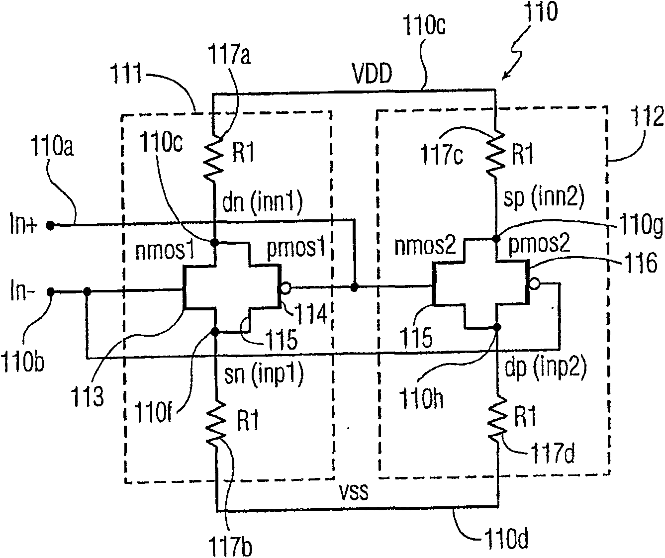
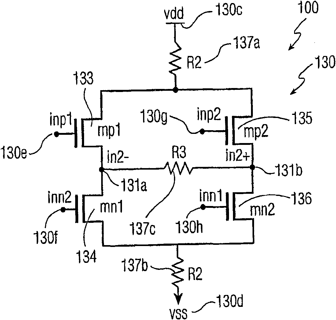
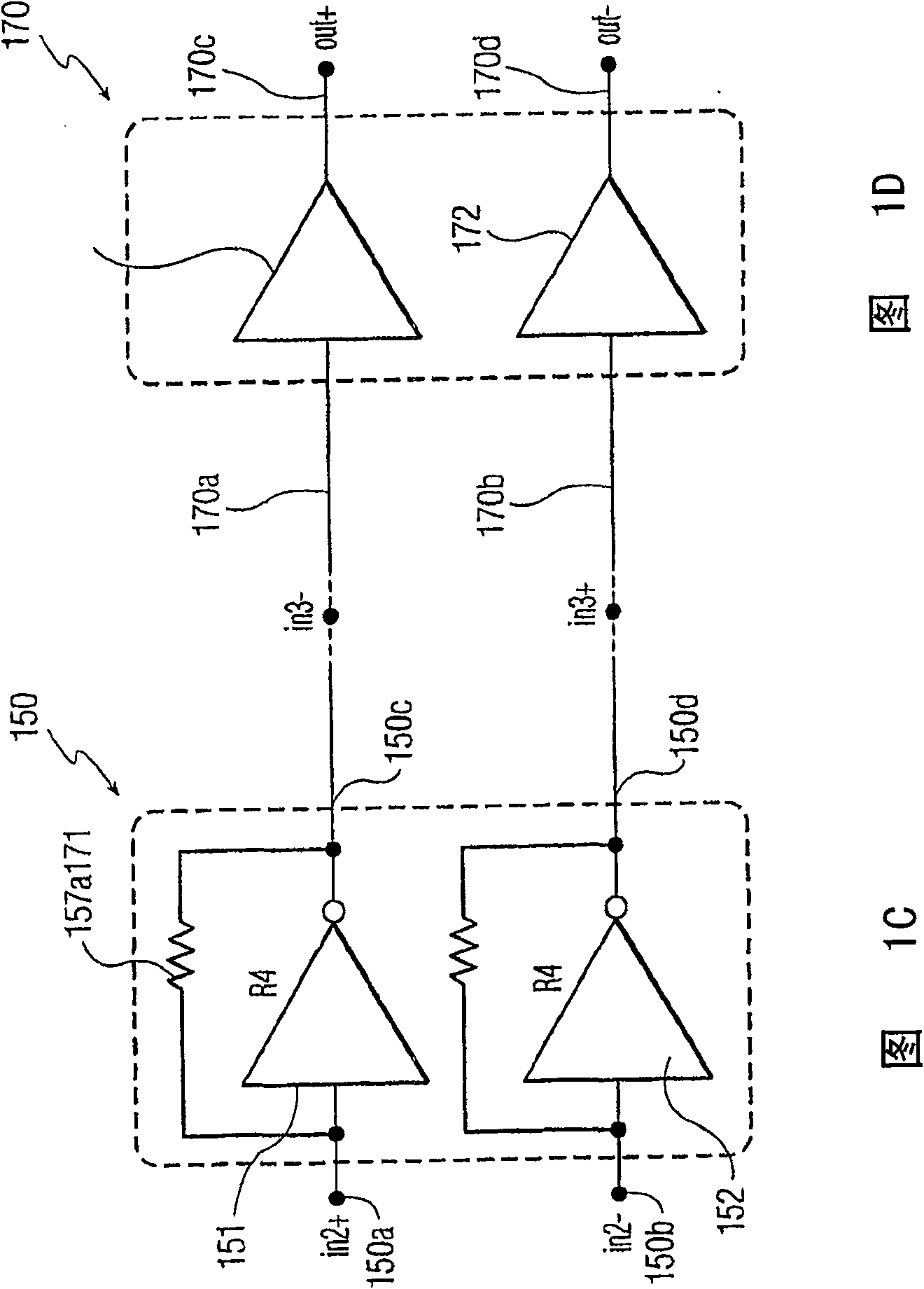
[0020] Figures 1a through 1d show various stages of a rail-to-rail common-mode voltage (CMV) differential receiver circuit 100 in accordance with a preferred embodiment of the present invention. The differential receiver circuit 100 includes four stages of symmetrical circuits arranged in series. Figure 1a shows a differential signal splitter input stage 110 as the first stage. FIG. 1 b shows the second stage, the CMV normalization stage 130 . FIG. 1c shows the third stage, the transimpedance amplifier stage 150 . FIG. 1d shows the fourth stage, which acts as a buffer stage for the rail-to-rail output driver stage 150 .

[0021] Referring to FIG. 1 a , the first stage 110 includes two symmetrical circuit branches, a first branch 111 and a second branch 112 . Arranged within the first branch 111 are a first n-channel metal oxide semiconductor (NMOS) transistor ( NMOS1 ) 113 and a first p-channel metal oxide semiconductor (PMOS) transistor ( PMOS1 ) 114 . Arranged within the...


PUM


Abstract

A novel high-speed differential receiver (100) is disclosed that provides a apparatus receiving and amplifying a small differential voltage with a rail-to-rail common mode voltage. The receiver output signals are differential signals with low skew and high symmetry. This high-speed differential receiver (100) is based on a common mode voltage normalization, which is based on a differential phase splitting methodology, before the resulting signal is recombined, normalized and amplified. The method involves using a differential signal splitting stage (110) followed by a common mode voltage normalization stage (130), then a controlled gain transimpedance amplification stage (150), and then amplification using one or two rail to rail amplification stages (170) that are symmetrical and balanced in nature.

Description

technical field [0001] The present invention relates to the field of differential receiver circuits, and more particularly, to differential receiver circuits for rail-to-rail common mode operation with low skew and symmetrical differential output signals. Background technique [0002] One conventional technique for receiving low-swing differential signals with a rail-to-rail common-mode voltage (CMV) range utilizes two receiver circuits. The first receiver circuit is, for example, an NMOS type input transistor used to receive a signal having a CMV close to the power supply voltage potential (Vdd); and a NMOS type input transistor used to receive a signal having a CMV close to the ground potential (gnd) PMOS type input transistor. The output signals from the two receiver circuits are then combined into a single-ended output signal from its output. Differential receiver circuits typically have any form of differential amplifier, however, the most common differential amplifie...

Claims


Application Information

Patent Timeline
Patent Type & Authority Patents(China)
IPC IPC(8): H03F3/26H03F3/30H03F3/45
CPCH03F3/45237H03F3/3061H03F3/45704H03F3/265H03F2203/45401
Inventor E·G·克豪里D·塞斯安斯
Owner NXP BV
Features
  • R&D
  • Intellectual Property
  • Life Sciences
  • Materials
  • Tech Scout
  • Unparalleled Data Quality
  • Higher Quality Content
  • 60% Fewer Hallucinations
Learn More