Supercharge Your Innovation With Domain-Expert AI Agents!

Ship, gas transfer station and method for feeding energy to gas transfer station from ship

A transfer station, gas technology, applied in the method of container discharge, gas/liquid distribution and storage, fluid transfer, etc., can solve problems such as cost

Inactive Publication Date: 2010-01-13
SN DETUDE & DE CONSTR DE MOTEURS DAVIATION (S N E C M A)
View PDF5 Cites 0 Cited by
  • Summary
  • Abstract
  • Description
  • Claims
  • Application Information

AI Technical Summary

Problems solved by technology

[0016] In addition, seawater causes sediment to be deposited within the ballast tank 142, which will incur substantial expense to remove it later

Method used


Image

  • Ship, gas transfer station and method for feeding energy to gas transfer station from ship
  • Ship, gas transfer station and method for feeding energy to gas transfer station from ship
  • Ship, gas transfer station and method for feeding energy to gas transfer station from ship

Examples


Embodiment Construction

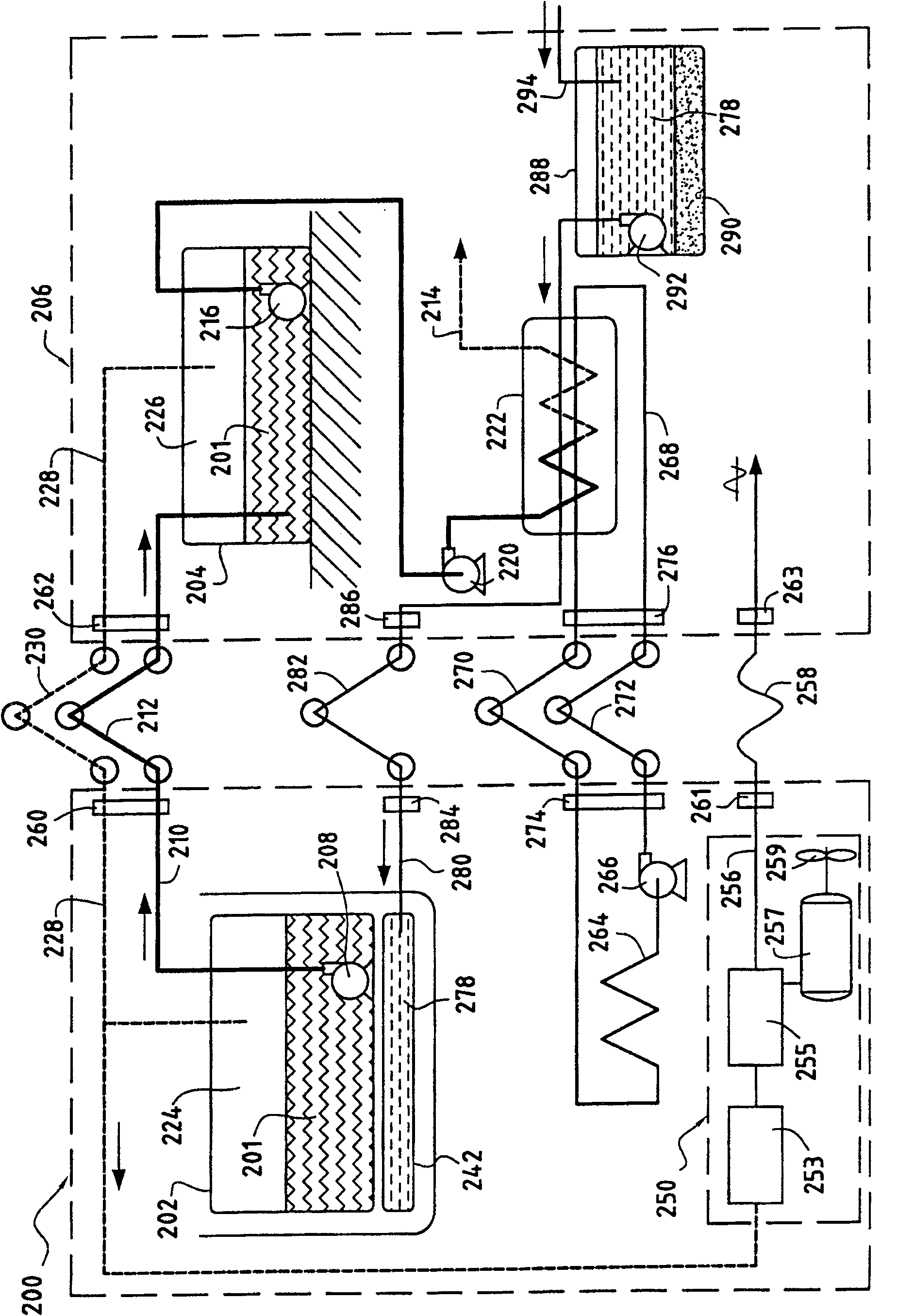
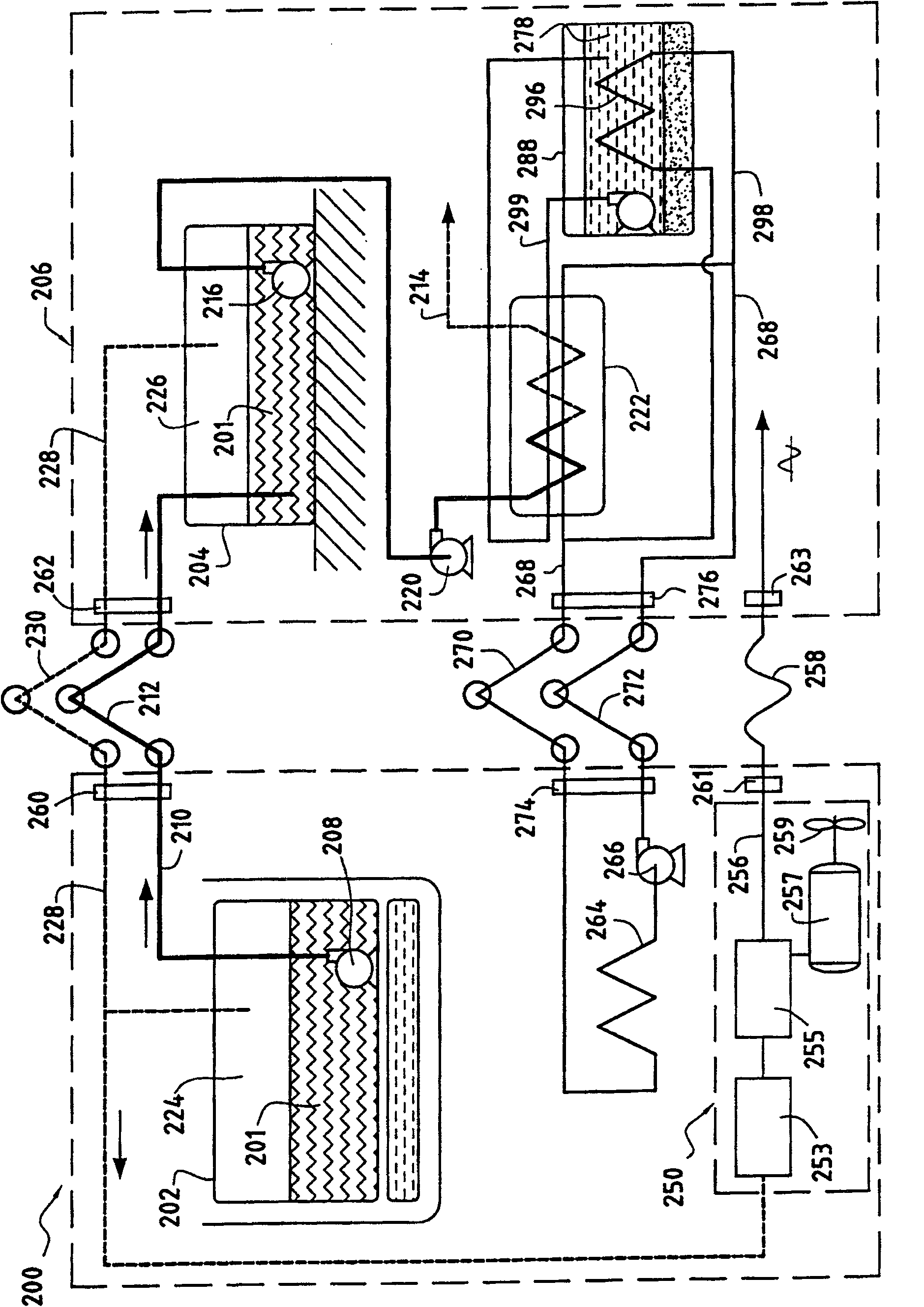
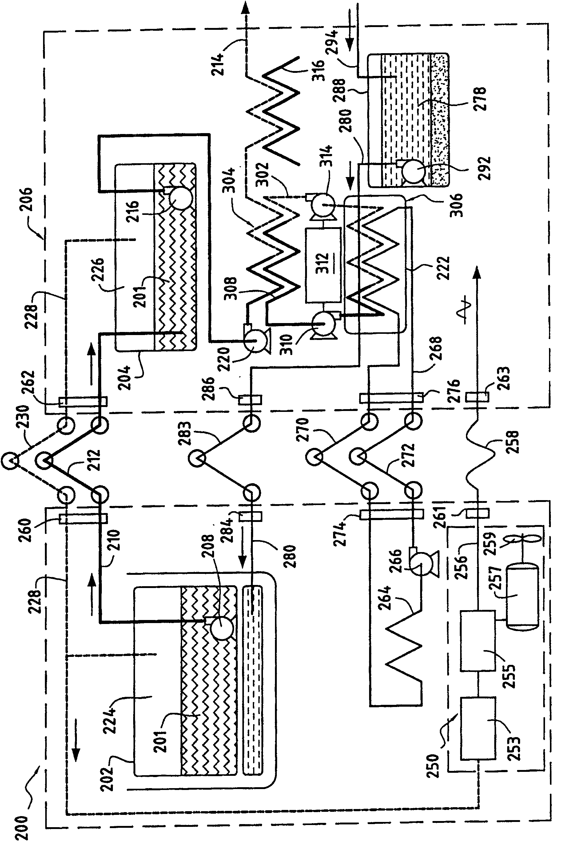
[0053] According to the present invention, it is indicated Figures 1 to 6 It represents a route for feeding energy from a ship 200 transporting liquefied gas 201 to a gas transfer station 206 and simultaneously transporting the liquefied gas 201 between a tank 202 of the ship 200 and a tank 204 of the gas transfer station 206 .

[0054] Vessel 200 has a propulsion system 250 that generates energy, a quantitative portion of which is delivered to gas transfer station 206 .

[0055] For example, the liquefied gas 201 may be liquefied natural gas, in which case the ship is a methane carrier and the gas transfer station is a methane transfer station. The liquefied gas 201 may also be liquefied petroleum gas.

[0056] figure 1 It is a schematic diagram of a line for unloading the liquefied gas 201 from the ship 200 that transports the liquefied gas to the gas transfer station 206 .

[0057] The liquefied gas 201 transported in the tank 202 of the ship 200 is unloaded to the tank ...


PUM


Abstract

A method of feeding the gas terminal (206) with energy from the ship (200) when transferring liquefied gas between a tank (202) of the liquefied gas transport ship (200) and a tank (204) of the gas terminal (206) is provided. The method delivers a portion of the energy produced by a propulsion system (250) of the ship (200) to the gas terminal (206).

Description

technical field [0001] This invention relates to the general field of transport of liquefied gas between ships and gas transfer stations. In particular, it relates to a method for supplying energy from a ship to a gas transfer station, and to a corresponding device for carrying out the method. Background technique [0002] It is known that natural gas is transported in vapor or liquid form by means of special interfaces between ships and gas transfer stations. [0003] Figure 7 is a simplified diagram of a prior art gas unloading circuit. [0004] The liquefied gas 101 transported in the tank 102 of the ship 100 is discharged to the tank 104 of the gas transfer station 106 by a pump 108 submerged in the tank 102 of the ship 100 . The liquefied gas is discharged into the tank 104 of the gas transfer station by means of a line 110 comprising a transfer arm 112 which allows a certain amount of free movement between the ship 100 and the gas transfer station 106 . [0005] Th...

Claims


Application Information

Patent Timeline
Patent Type & Authority Patents(China)
IPC IPC(8): B63B27/00B65G67/60B63B27/24B63B25/08B63B25/16B63J3/02F17C9/04F17C13/00
CPCF17C2223/0161Y02T70/90B63J3/02F17C2225/0161F17C2265/07F17C2221/035F17C2223/033F17C2227/0135F17C9/04F17C2225/0153F17C2265/03F17C2270/0123F17C2221/033F17C2270/0105Y02T70/5281F17C2225/033F17C2270/0136F17C2227/0178F17C2223/0153F17C2205/0323B63B27/24Y02T70/00Y02T70/50B63B25/08
Inventor 达米安·费热
Owner SN DETUDE & DE CONSTR DE MOTEURS DAVIATION (S N E C M A)
Features
  • R&D
  • Intellectual Property
  • Life Sciences
  • Materials
  • Tech Scout
  • Unparalleled Data Quality
  • Higher Quality Content
  • 60% Fewer Hallucinations
Learn More