Medical tower crane rotary arm

A technology of slewing arms and slewing arms, which is applied in the field of slewing arms, can solve problems such as heavy weight of the workbench, potential safety hazards, shaking, etc., and achieve the effects of relatively stable movement, reliable positioning, and smooth and slow movement

Active Publication Date: 2010-02-24
刘春海
View PDF4 Cites 2 Cited by
  • Summary
  • Abstract
  • Description
  • Claims
  • Application Information

AI Technical Summary

Problems solved by technology

In actual use, the workbench needs to rotate, and the same type of rotary mechanism has the problem of low degree of rotary control when it rotates
Due to the heavy weight of the workbench, a slight thrust will generate a large inertia, which will make the workbench rotate and shake quickly and greatly
However, some items on the workbench during the operation cannot be shaken, so such a rotary mechanism brings great inconvenience to the operation operator, and at the same time, there are also some potential safety hazards.

Method used


Image

  • Medical tower crane rotary arm
  • Medical tower crane rotary arm
  • Medical tower crane rotary arm

Examples


Embodiment Construction

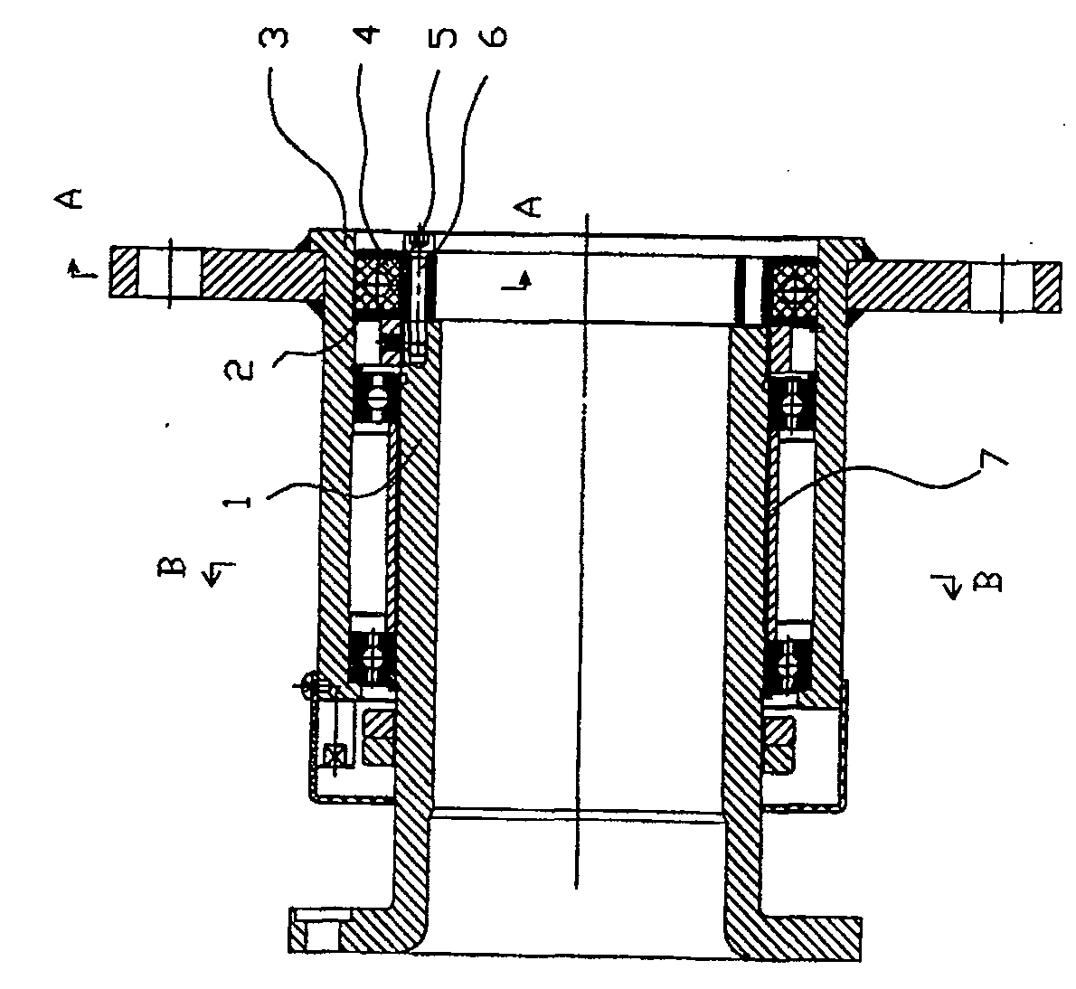
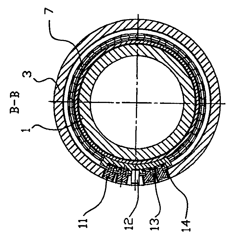
[0017] The present invention comprises the arm cover 3 and the hollow arm 1 which is arranged in the arm cover 3 and can rotate freely. between dampers.

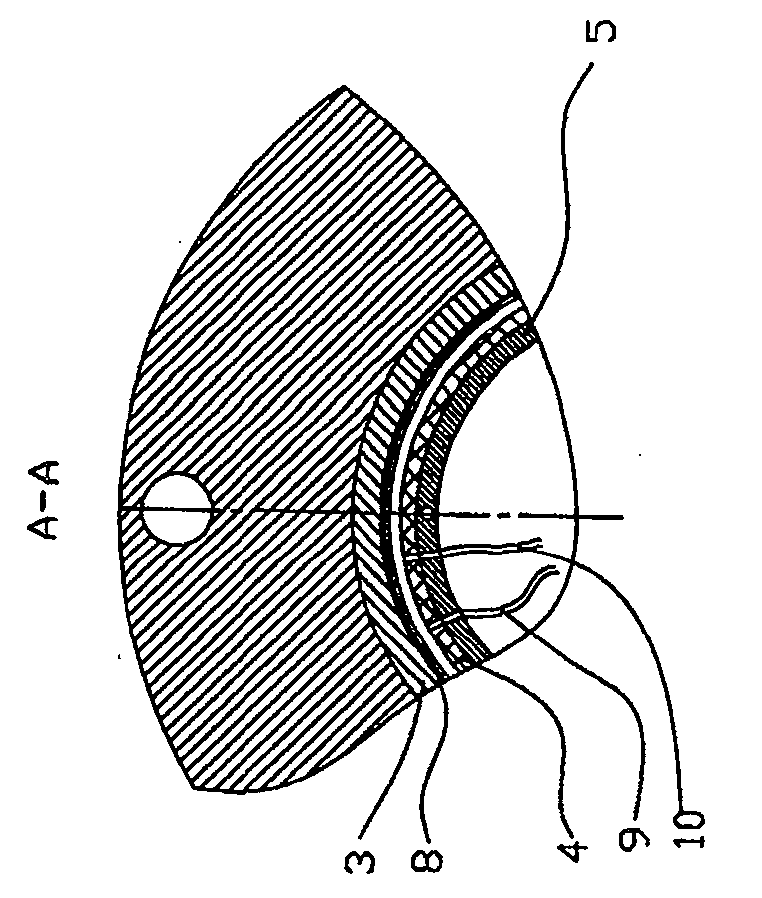
[0018] Brakes such as figure 1 , 2 , consisting of a brake disc 5 arranged on the end face of the hollow arm 1, an air pressure expansion ring 4 arranged on the outer ring of the brake disc 5, an air source, and an air pressure control device for the expansion ring 4; the brake disc 5 is coaxial with the hollow arm 1 , is fixedly connected by connecting screw 6, and its outer end is located in the 3 pockets of the arm cover; the air pressure expansion ring 4 is fixedly connected on the surface of the brake disc 5 edge; the air pressure expansion ring 4 is connected to the air source and the air pressure control device through the trachea. In order to make the positioning of the air pressure expansion ring 4 reliable, a circle of grooves 2 is provided on the edge of the brake disc 5, and the air pressure expansion ring 4 is...


PUM


Abstract

The invention relates to a swinging jib for a medical tower crane, which comprises a swinging jib sleeve, a hollow swinging jib which is arranged in the swinging jib sleeve and is connected with the swinging jib sleeve through a bearing, a brake apparatus arranged on the end surface of the hollow swinging jib, and a damping device arranged between the hollow swinging jib and the swinging jib sleeve, wherein the brake apparatus consists of a brake disc arranged on the end surface of the hollow swinging jib, an air pressure expansion ring arranged at an outer ring of the brake disc, an air source, and an expansion ring air pressure control device; and the damping device consists of a copper bushing and a connecting device which is arranged on the swinging rib sleeve and is connected with thecopper bushing. The swinging jib for the medical tower crane can ensure that a worktable is steady and slow during the movement and can stay still when the worktable moves to the required position, thereby ensuring that the worktable is steady and has reliable positioning.

Description

technical field [0001] The invention relates to a rotary arm of a medical pendant, in particular to a pneumatic limit braking device and a mechanical damping device of the rotary arm of a medical pendant. Background technique [0002] The lower part of the pendant tower in the medical operating room is equipped with a workbench, where some surgical instruments, instruments and meters are placed. In actual use, the workbench needs to rotate, and the same kind of rotary mechanism has the problem of low degree of rotary control when it rotates. Due to the heavy weight of the workbench, even a slight thrust will generate a large inertia, which will make the workbench rotate and shake rapidly and greatly. And some items on the workbench during the operation cannot be shaken, so such a rotary mechanism brings great inconvenience to the operation operator, and at the same time, there are also some potential safety hazards. Contents of the invention [0003] Aiming at the above ...

Claims


Application Information

Patent Timeline
Patent Type & Authority Patents(China)
IPC IPC(8): F16D49/14A61B19/02A61B90/00
Inventor 刘春海
Owner 刘春海
Why Eureka
Try Eureka