Inlet sealing and connecting device used for waste-heat boiler

A waste heat boiler and inlet sealing technology, which is applied in the field of sealing connection devices, can solve problems such as increased energy consumption, manual dust removal, and complicated operation, and achieve the effects of good sealing performance, reduced power consumption, and simple operation

Active Publication Date: 2010-03-24
CHINA ENFI ENGINEERING CORPORATION
View PDF6 Cites 1 Cited by
  • Summary
  • Abstract
  • Description
  • Claims
  • Application Information

AI Technical Summary

Problems solved by technology

The refractory brick structure is not flexible. Therefore, the sealing of this connection structure is poor, and the smoke leakage in the gap is large. The air leakage rate is generally 40%-80%. It is difficult to treat the tail gas at the rear; Corrosion will occur; again, energy is wasted, and the heat taken away by air leakage and cooling water cannot usually be recycled. Due to air leakage, the energy consumption of the induced draft fan and rear exhaust gas treatment will increase. Finally, the operating environment is poor. There are large gaps between them, and the flue gas often escapes, polluting the operating environment, and the refractory brick sealing structure is seriously dusty, requiring manual cleaning, while the water-cooled water jacket structure has a short life, and the water jacket structure cools the heat absorbed by the flue gas. Taken away by the cooling water, not being used and wasting energy
[0004] In addition, when an accident needs to be inserted between the waste heat boiler inlet and the smelting furnace flue gas outlet, the refractory brick structure needs to be removed, and then the flue ram is inserted between the waste heat boiler inlet and the smelting furnace flue gas outlet In between, the flue shutter is finally pulled out, and refractory bricks are built again. In other words, the refractory brick structure is one-time, so the operation is complicated, time-consuming and costly
In the case of the water-cooled water jacket structure, the flue gate must be removed before it can be inserted, which is complicated to operate and low in efficiency

Method used


Image

  • Inlet sealing and connecting device used for waste-heat boiler
  • Inlet sealing and connecting device used for waste-heat boiler
  • Inlet sealing and connecting device used for waste-heat boiler

Examples


Embodiment Construction

[0032] Embodiments of the present invention are described in detail below, examples of which are illustrated in the accompanying drawings, wherein like reference numerals refer to like elements throughout. The embodiments described below are used to explain the present invention by referring to the figures, and the embodiments are exemplary and should not be construed as limitations of the present invention.

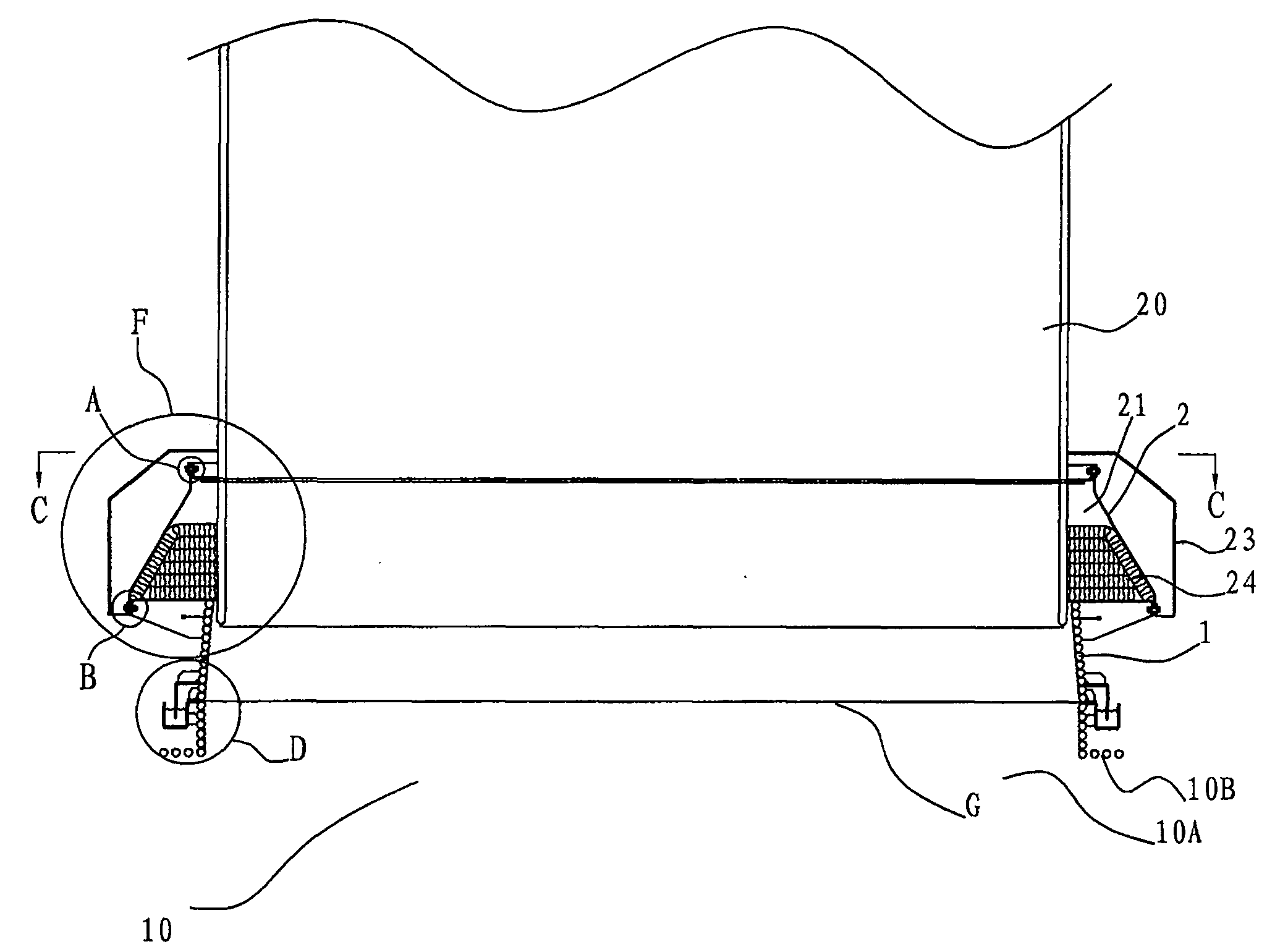
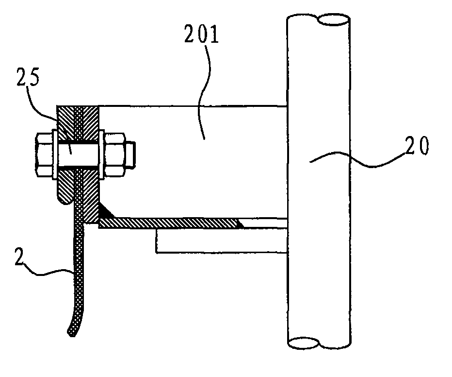
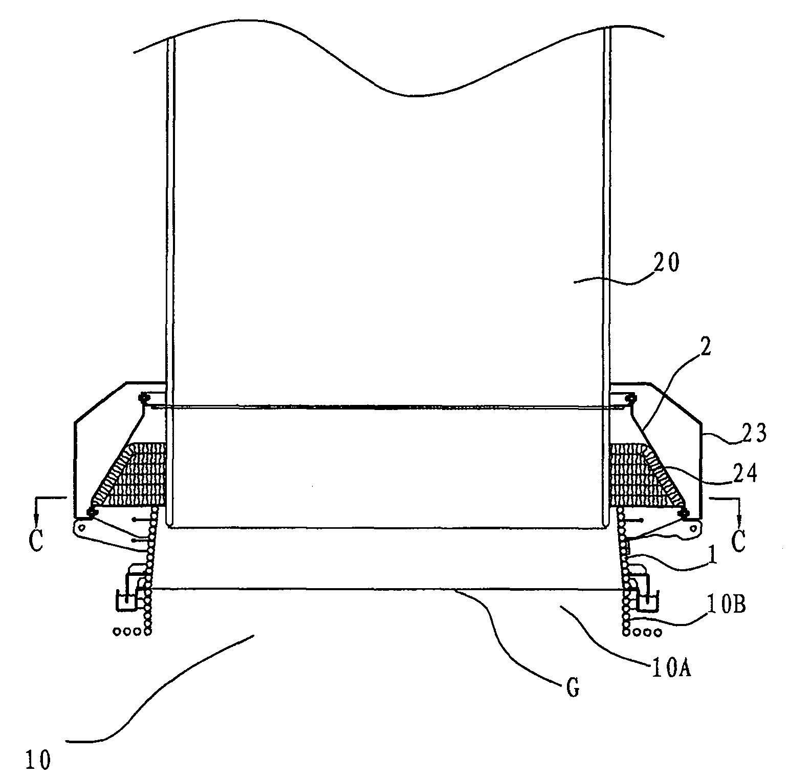
[0033] see Figure 1 to Figure 8 , according to the embodiment of the present invention, the inlet sealing connection device for the waste heat boiler includes a lower sealing connection part 1 and a flexible sealing connection part 2, and the lower sealing connection part 1 is suitable for buckling on the top of the melting furnace 10, that is, Buckled on the flue gas outlet 10A of the smelting furnace 10, it should be noted that, on the flue gas outlet 10A of the smelting furnace 10, a flue gas outlet cover 10B is generally provided, and the lower sealing connector 1 i...


PUM


Abstract

The invention discloses a connection device used for sealing entrance of waste heat boiler, comprising a lower part sealing connection piece which is buttoned up at the flue gas exit of melting furnace, and a flexible sealing connection piece one end of which is suitable to be in sealed connection with the waste heat boiler and the other end of which is in sealed connection with the lower part sealing connection piece, thus the flexible sealing connection piece and the lower part sealing connection piece can move relative to the waste heat boiler. The sealing connection device of the inventionis composed of the lower part connection part and the flexible connection part, wherein, the flexible connection part is provided with expansion margin, thus satisfying thermal expansion when in performance and avoiding the occurrence of gap due to the thermal expansion of the waste heat boiler and the melting furnace. Therefore, the connection device used for sealing entrance of waste heat boiler has the advantages of fine sealing performance, simple operation and low cost.

Description

technical field [0001] The invention relates to a sealing connection device used between a waste heat boiler and a smelting furnace, in particular to a sealing connection device installed between the waste heat boiler inlet and the flue gas outlet of the smelting furnace. Background technique [0002] In the field of smelting, the waste heat boiler is used to recover the heat of the high-temperature flue gas discharged from the smelting furnace. In the prior art, a refractory brick structure or a water-cooled water jacket structure is used between the smelting furnace and the waste heat boiler to form a sealed flue structure. . The high-temperature flue gas discharged from the smelting furnace enters the waste heat boiler, and the waste heat boiler takes away the heat energy of the high-temperature flue gas through heat exchange and transports it to the end user. [0003] Since the smelting furnace and the waste heat boiler expand and deform when subjected to high temperatu...

Claims


Application Information

Patent Timeline
Patent Type & Authority Patents(China)
IPC IPC(8): F22B1/16
Inventor 徐建炎陈逢胜王岗
Owner CHINA ENFI ENGINEERING CORPORATION
Why Eureka
Try Eureka