Equipment for automatic assembling of heat conducting tube and radiation fins

A technology for radiating fins and assembling equipment, applied in the direction of heat exchange equipment, etc., can solve the problems of manual replacement operations prone to negligence, increase in defect rate, deformation of heat pipes, etc.

Active Publication Date: 2007-07-25
HUANG TSUNG HSIEN YUAN SHAN HSIANG
View PDF0 Cites 9 Cited by
  • Summary
  • Abstract
  • Description
  • Claims
  • Application Information

AI Technical Summary

Problems solved by technology

[0002] The traditional heat sink module composed of heat pipes consists of a plurality of heat dissipation fins (aluminum or copper), one or more heat pipes and a base (commonly known as a copper base). A fan lock frame can be combined as needed to lock and fix a heat dissipation fan; the known assembly method of heat dissipation fins and heat pipes is to fix the heat pipes to the upper die of the stamping die with a clamp in advance, and use a punching machine The stamping assembly is completed, but after the completion, the punching machine must be shut down first, and then the upper mold clamping tool must be taken out and replaced ...

Method used


Image

  • Equipment for automatic assembling of heat conducting tube and radiation fins
  • Equipment for automatic assembling of heat conducting tube and radiation fins
  • Equipment for automatic assembling of heat conducting tube and radiation fins

Examples


Embodiment Construction

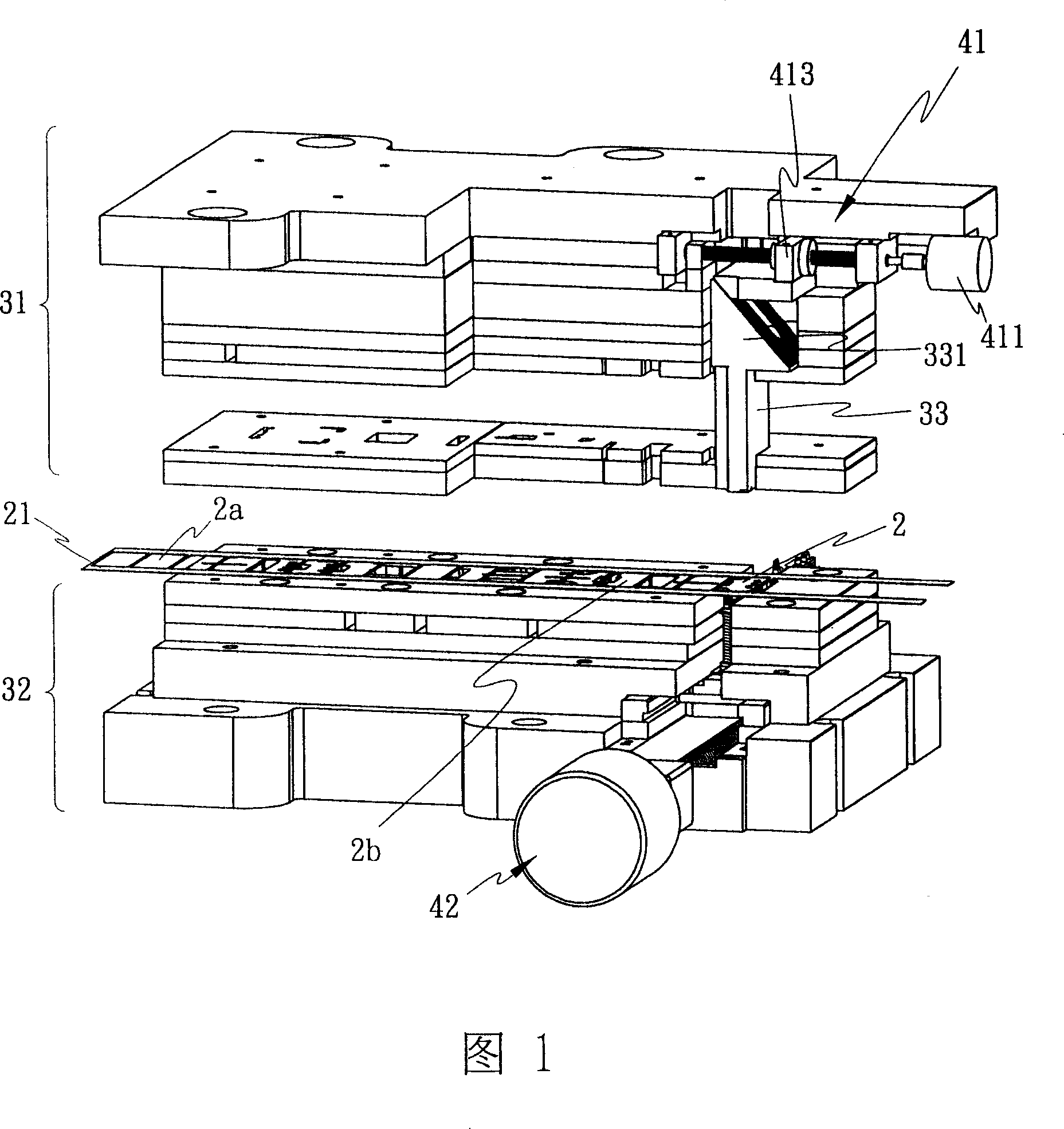
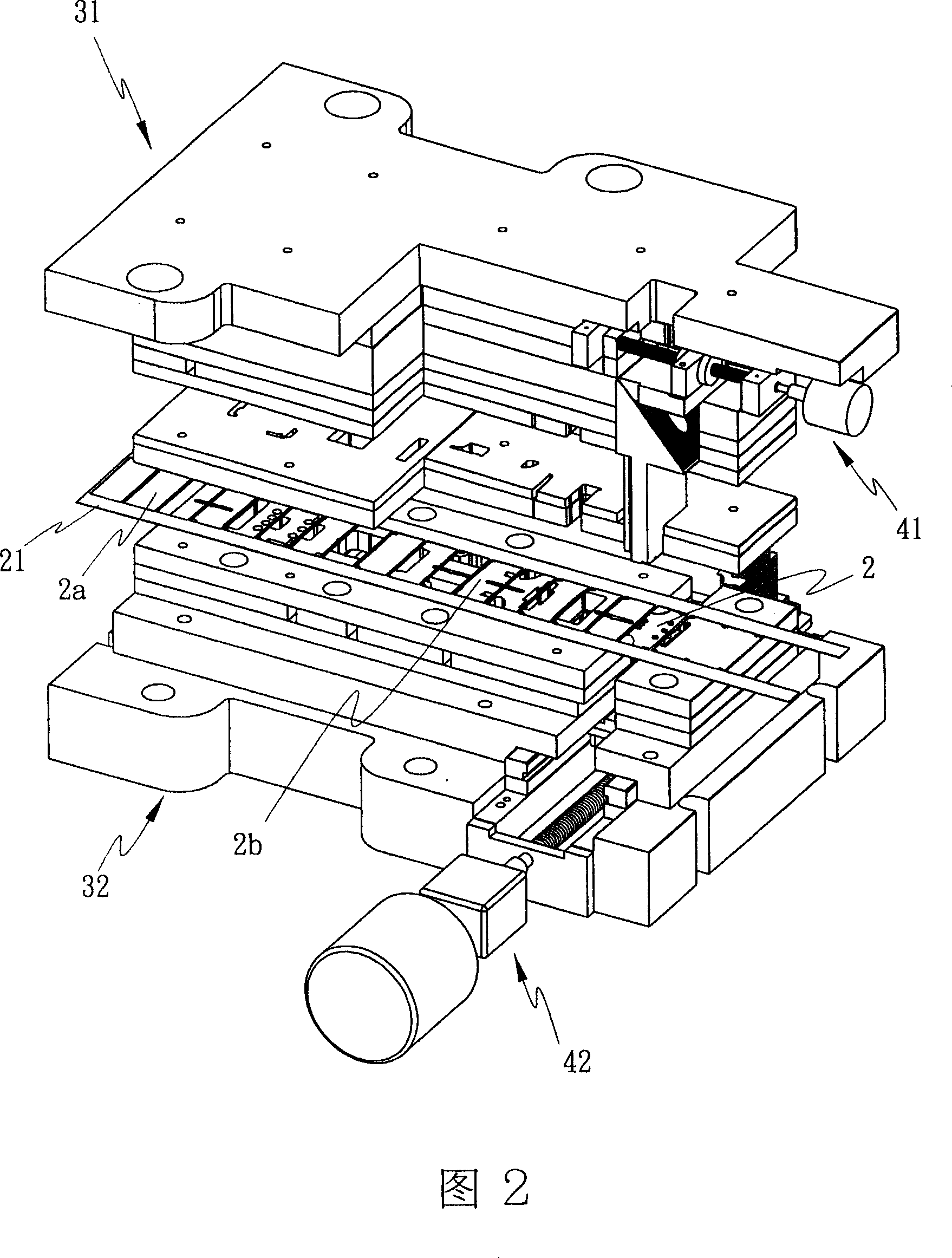
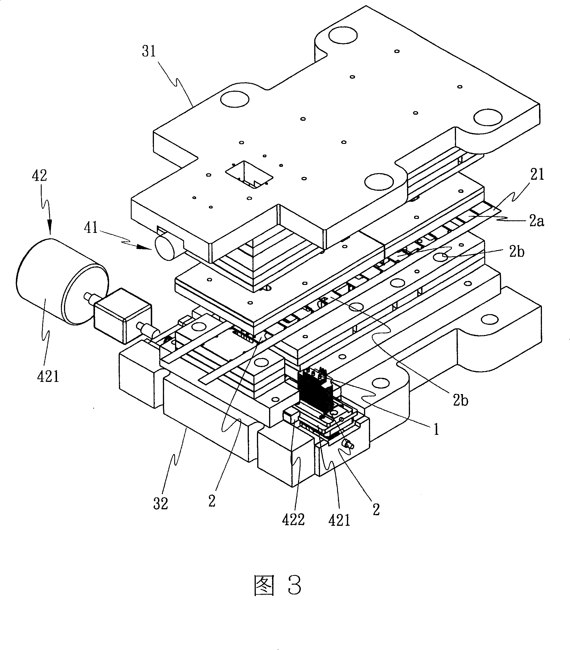
[0019] As shown in Figures 1 to 4, the automatic assembly equipment for heat pipes and radiating fins of the present invention is mainly composed of a continuous stamping die device 3 and two upper and lower transmission mechanisms 41, 42, in which:

[0020] The continuous die device 3 is composed of an upper die 31, a lower die 32 and a punch 33 provided in the upper die 31. In order to cooperate with an automatic feeding device (not shown), the material 2a for the heat dissipation fins including the strip 21 is selected. , The semi-finished fins 2b to the finished product 2 (as shown in Figure 5) are gradually made through the segmented punching process, and the finished fins 2 are accurately delivered to the working position above the worktable 421 of the lower transmission mechanism 42 (such as 6), the finished heat dissipation fin 2 is now completely formed, and has one or more through holes 22 that can be closely matched with the heat pipe 1 to provide one or more heat Cathe...


PUM


Abstract

An automatic assembling apparatus for the heat conducting tube and heat radiating fins is composed of a continuous punching die unit with upper and lower dies, and upper and lower drive units arranged respectively in said upper and low dies. Said continuous punching die unit can punch the heat radiating fins and fixing them onto a heat conducting tube. Said upper drive unit can damp the punch head. Said lower drive unit can clamp said tube and move the finished product out.

Description

Technical field [0001] The invention provides an automatic assembly equipment for heat pipes and radiating fins, which is composed of a continuous stamping die device and two upper and lower transmission mechanisms. The radiating fins punched in the continuous stamping die are used by the upper The upper transmission mechanism in the mold causes the punch to produce an automatically decreasing step stroke, so that the radiating fins are tightly sleeved into the heat pipe from bottom to top, and the assembly is completed quickly. Background technique [0002] The traditional radiator module composed of heat pipes consists of a plurality of heat dissipation fins (aluminum or copper), one or more heat pipes and a base (commonly known as copper bottom), which are arranged around the heat dissipation fins. A fan lock frame can be combined as needed to provide a cooling fan lock fixed position; the known assembly method of cooling fins and heat pipes is to fix the heat pipe to the uppe...

Claims


Application Information

Patent Timeline
IPC IPC(8): B21D53/08B21D39/00
Inventor 黄崇贤
Owner HUANG TSUNG HSIEN YUAN SHAN HSIANG
Why Eureka
Try Eureka