Electrolytic lathe working method

A processing method and electrolytic car technology, applied in electric processing equipment, electrochemical processing equipment, processing working medium, etc., can solve the problems of low efficiency, high cost, low quality of processing surface, etc., and achieve strong localization and good control. , the processing effect is good

Inactive Publication Date: 2007-07-25
HARBIN INST OF TECH
View PDF0 Cites 30 Cited by
  • Summary
  • Abstract
  • Description
  • Claims
  • Application Information

AI Technical Summary

Problems solved by technology

[0005] In order to overcome the defects of low efficiency, high cost and low surface quality of traditional mechanical processing and other ...

Method used


Image

  • Electrolytic lathe working method
  • Electrolytic lathe working method

Examples


Embodiment Construction

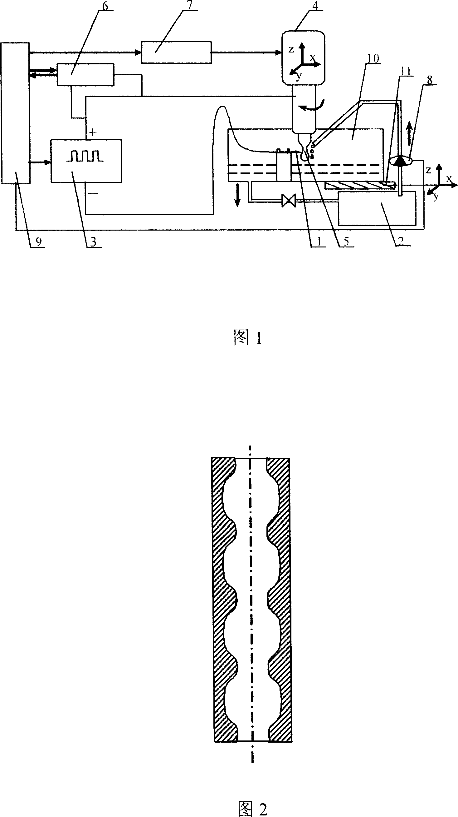
[0027] Below in conjunction with Fig. 1, this implementation mode is specifically described, and this implementation mode includes the following steps

[0028] The tool cathode 1 is fixed in the electrolyte tank 10, the electrolyte tank 10 is fixed on the movable machine tool table, and the workpiece anode 5 is fixed on the machine tool;

[0029] Bringing the tool cathode 1 into contact with the workpiece anode 5;

[0030] The processing gap between the tool cathode 1 and the workpiece anode 5 is set, and the circulating electrolyte provided by the electrolyte pump 8 flows through the gap, and the working current between the tool cathode 1 and the workpiece anode 5 flows through the electrolyte in the processing gap. Dissolving workpiece anode 5 for processing;

[0031] The workpiece anode 5 is fixed on the lower end of the main shaft 4 of the machine tool, and the workpiece anode 5 rotates at high speed during processing.

[0032] In the above steps, the rotational speed of...


PUM


Abstract

An electrolytic turning method for machining the internal and external rotary surfaces and their end face includes such steps as fixing the tool as cathode in the electrolyzer fixed onto a movable bench of machine-tool, fixing the workpiece as anode to the lower end of a mainshaft of machine-tool, regulating the gap between said cathode and anode, and using an electrolyte pump to make the electrolyte to cyclically flow through said gap while machining the workpiece.

Description

technical field [0001] The invention relates to an electrolytic turning processing method used in the field of special processing, which is mainly used for processing various inner and outer rotating surfaces and their end faces. Background technique [0002] At present, the processing used in mechanical manufacturing can be divided into traditional mechanical processing and unconventional mechanical processing. [0003] Traditional machining relies on the tool material being harder than the workpiece, and using mechanical energy to remove excess material from the workpiece is generally feasible. However, when the workpiece material is getting harder and the processing surface is complex, the traditional machining will limit the productivity and affect the processing quality; There is a mechanical force in the processing, it is easy to damage the workpiece to be processed, and it is difficult to complete the processing task. [0004] Unconventional mechanical processing is...

Claims


Application Information

Patent Timeline
IPC IPC(8): B23H3/00B23H7/26B23H7/14B23H7/18B23H3/08
Inventor 王振龙朱保国曾伟梁孙立忠
Owner HARBIN INST OF TECH
Why Eureka
Try Eureka