Gasification stove with multi nozzle, and gasification method

A gasifier and multi-nozzle technology, which is used in the gasification of granular/powdered fuel, combined combustion mitigation, etc., can solve the problems of short residence time of reactants, unsatisfactory conversion rate of gasification reaction, etc. The effect of prolonging residence time and improving conversion rate

Active Publication Date: 2007-07-25
CHNA ENERGY INVESTMENT CORP LTD +1
View PDF0 Cites 77 Cited by
  • Summary
  • Abstract
  • Description
  • Claims
  • Application Information

AI Technical Summary

Problems solved by technology

[0013] In summary, although many different types of gasifiers have been successfully applied in industry, they all have probl

Method used


Image

  • Gasification stove with multi nozzle, and gasification method
  • Gasification stove with multi nozzle, and gasification method
  • Gasification stove with multi nozzle, and gasification method

Examples


Embodiment approach 1

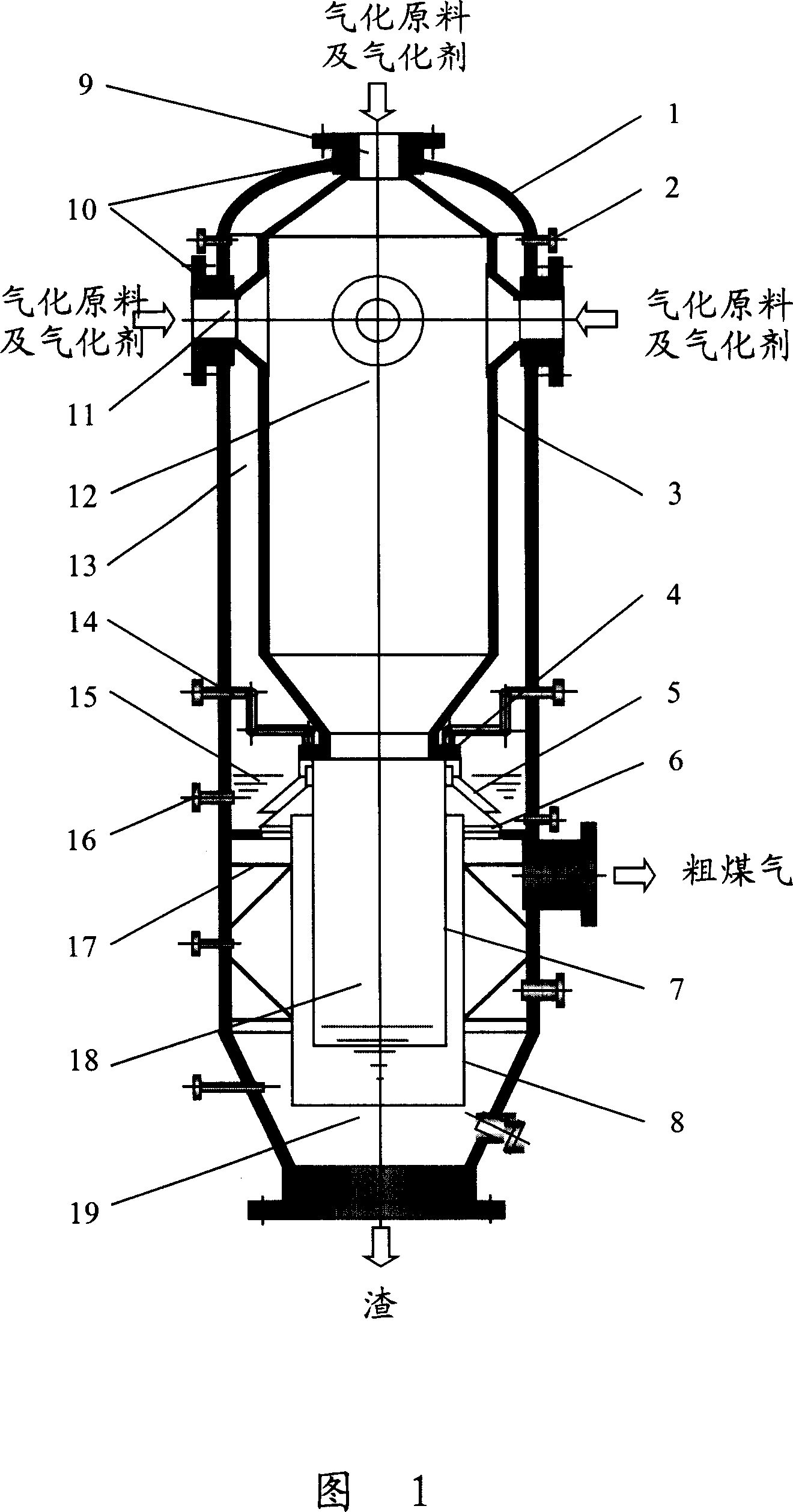
[0032] Figure 1 shows a cantilever-type multi-nozzle gasification furnace, which mainly includes the following components: furnace shell 1, furnace liner 3, chilling ring 4, water seal tank 15, guide tube 7, deflector tube 8, Top nozzle 9, side nozzle 11. The furnace gall, chilling ring, water seal groove, deflector tube, and baffle tube are arranged inside the furnace shell from top to bottom, and the above-mentioned components are preferably arranged coaxially from top to bottom, and are preferably arranged with the The furnace shell is set coaxially. The interior of the furnace is a gasification chamber 12 where the gasification raw material and the gasification agent fully contact to carry out the gasification reaction. The annular space formed between the furnace gall and the furnace shell is a thermal insulation chamber 13, and the space below the water seal groove 15 is a quenching chamber 18 for reactant flow.

[0033] In the gasifier, the top nozzle 9 is arranged on...

Embodiment approach 2

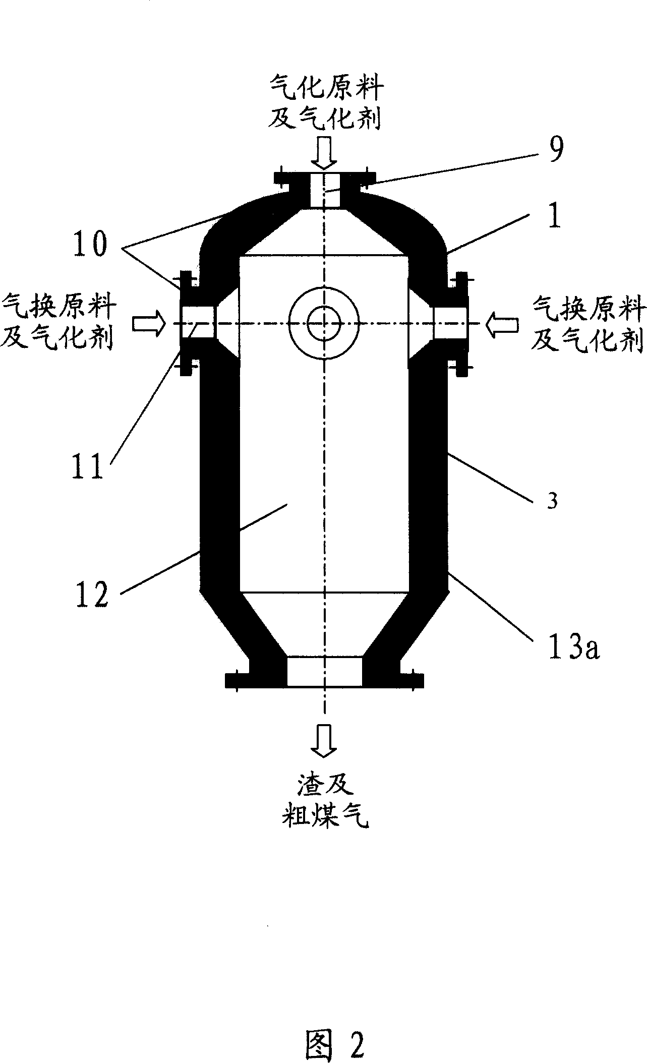
[0046] The gasifier shown in Fig. 2 is another implementation form of the present invention. It is a furnace structure filled with refractory insulation materials. The top nozzle 9 is arranged on the top of the gasification chamber 12, and the central axis of the top nozzle coincides with the central axis of the gasification chamber. The upper part of the gasification chamber 12 is provided with a layer of side nozzles 11 arranged according to the axial deflection angle and radial deflection angle required by the present invention. The refractory insulation material 13a is filled between the furnace 3 and the gasifier shell 1. The upper and lower heads of the furnace 3 and the nozzle installation interface adopt a coil structure, and the straight part adopts a coil structure or a membrane Type water wall structure. Gasification raw materials and gasification agents enter the gasification chamber 12 from the top nozzle 9 and the side nozzle 11 of the gasification furnace, and...

Embodiment approach 3

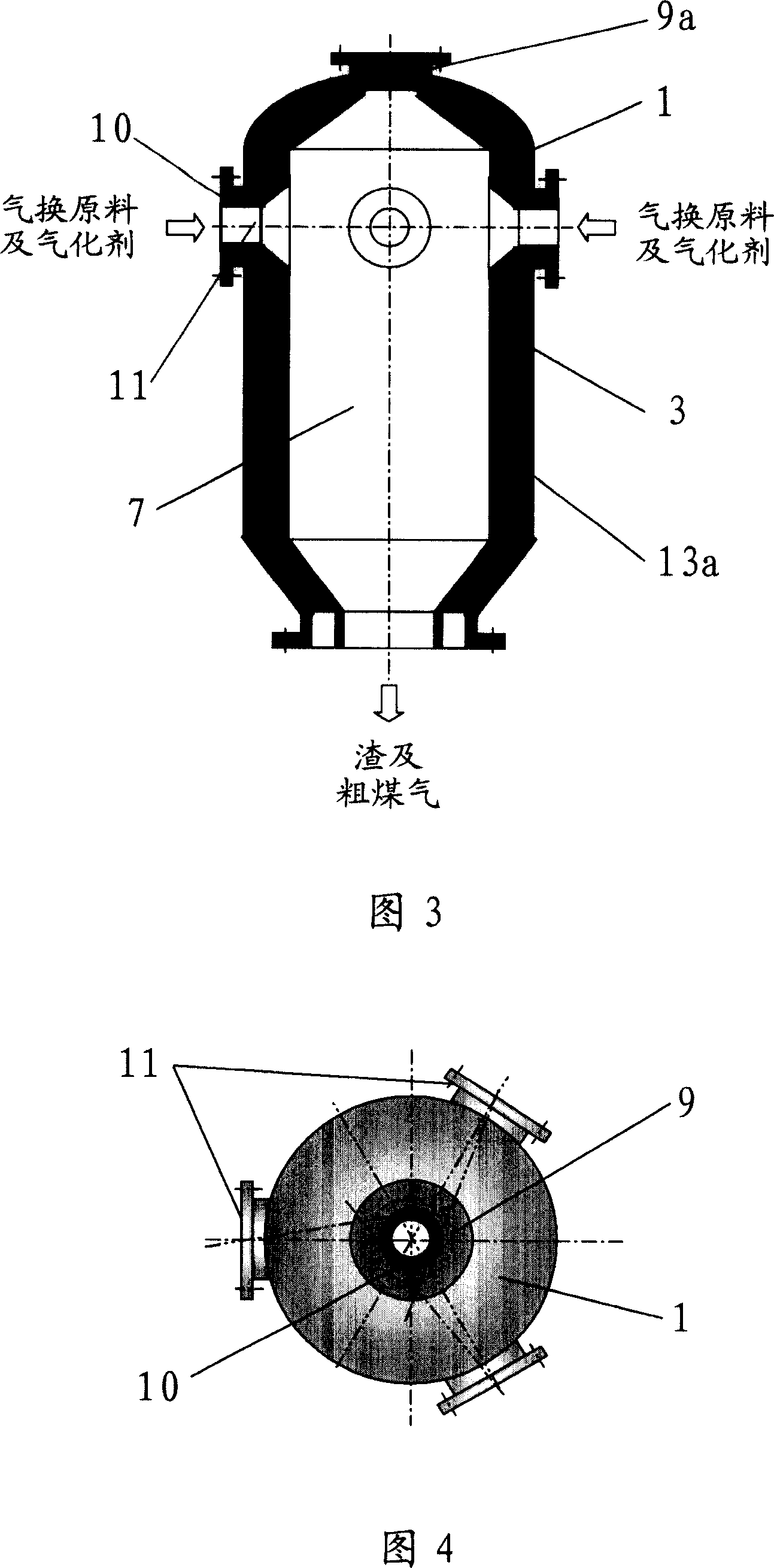
[0048] As shown in Figure 3, in the third embodiment of the present invention, the main structure of the gasification furnace is basically the same as that of the second embodiment, the only difference is that the gasification furnace does not have top nozzles for gasification raw materials and gasification agents , and only the side nozzle 11 is provided. A manhole 9a is provided on the top of the gasification chamber 12 to facilitate installation and maintenance of the equipment.


PUM


Abstract

This invention discloses a multi-nozzle gasifier, which comprises: a shell, a jacket and side nozzles. At least a layer of side nozzles is set at the middle-upside of the gasification chamber along circumferential direction. The axial deflection angle alpha is within 0-18 deg., and the radial deflection angle beta of the side nozzle is within 0-22.5 deg., wherein alpha and beta cannot be 0 deg. at the same time. This invention also provides a method for gasifying by using the multi-nozzle gasifier. The multi-nozzle gasifier is suitable for large-scale production of synthesis gas from coal and sulfur-containing fuel gas, can prolong the residence time of carbon-containing solid reactant, and has high gasification conversion rate.

Description

technical field [0001] The invention relates to a gasification device and a gasification method for producing crude coal gas mainly composed of carbon monoxide and hydrogen from carbon-containing fuels, more specifically, a multi-nozzle gasification furnace and a gasification furnace using the gasification furnace gasification method. Background technique [0002] As the foundation and core of clean coal technology, coal gasification technology has a history of more than 200 years. The development of modern coal gasification technology has benefited from the oil crisis. The first worldwide oil crisis in the 1970s made people realize that oil and natural gas are not unlimited resources compared with coal. In view of the prediction of the prospect of natural gas supply, the development of coal gasification as an alternative energy source has been brought back to the agenda, and the pace of development and industrialization of new coal gasification technology has been accelera...

Claims


Application Information

Patent Timeline
IPC IPC(8): C10J3/56
CPCY02E20/18
Inventor 任相坤高聚忠李红凯赵金立岳国
Owner CHNA ENERGY INVESTMENT CORP LTD
Why Eureka
Try Eureka