
Electronic device

A technology of electronic equipment and circuits, applied in the field of electronics, to achieve the effects of wide application, improved experience, and reduced leakage current

Active Publication Date: 2007-07-25
HUAWEI TECH CO LTD
View PDF0 Cites 2 Cited by
  • Summary
  • Abstract
  • Description
  • Claims
  • Application Information

AI Technical Summary

Problems solved by technology

[0006] According to the above analysis, it can also be known that if the live wire and the neutral wire are interchanged, leakage current will also be formed.

Method used


Image

  • Electronic device
  • Electronic device

Examples


Embodiment Construction

[0018] In order to make the object, technical solution and advantages of the present invention clearer, the present invention will be further described in detail below in conjunction with the accompanying drawings.

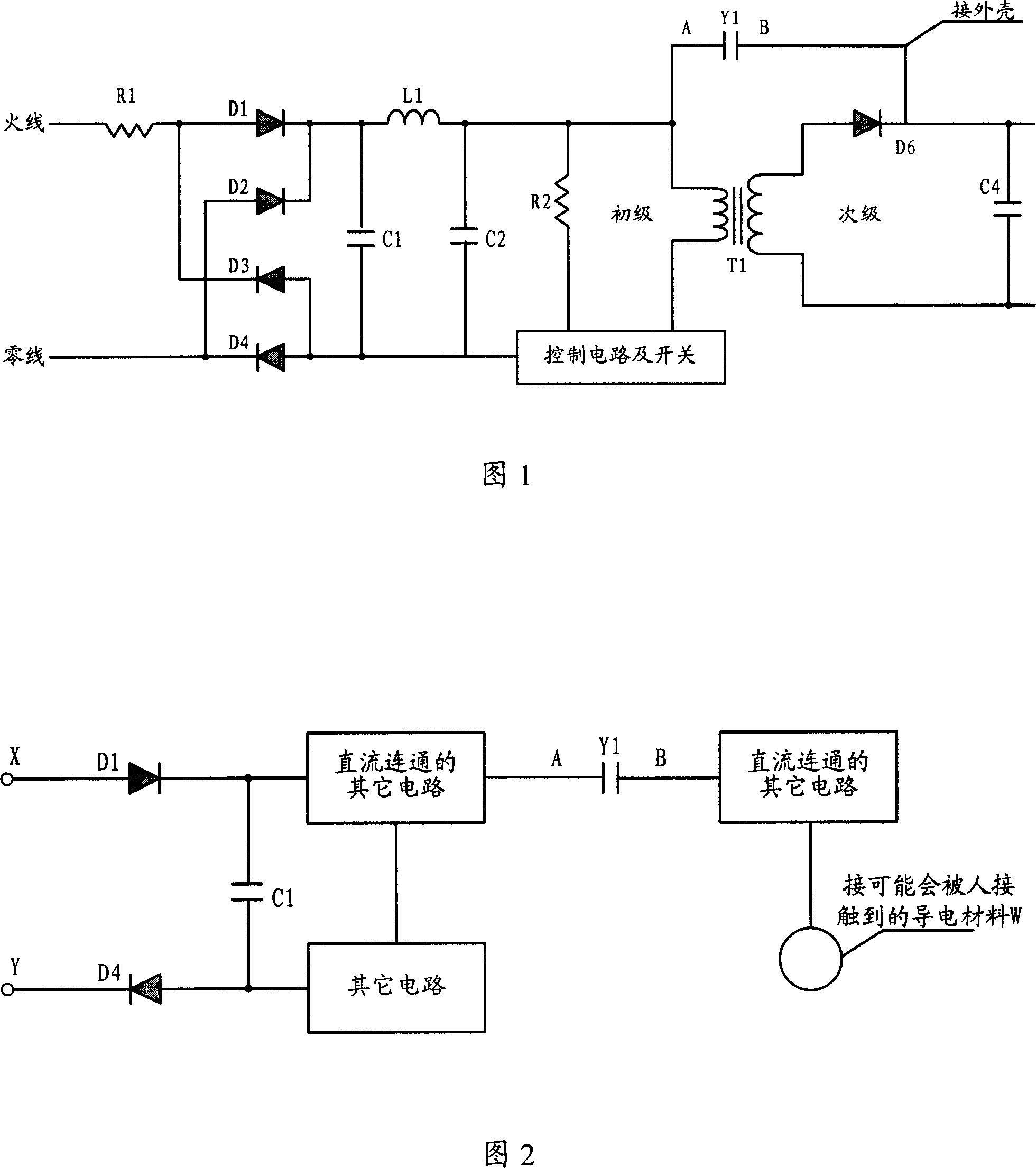
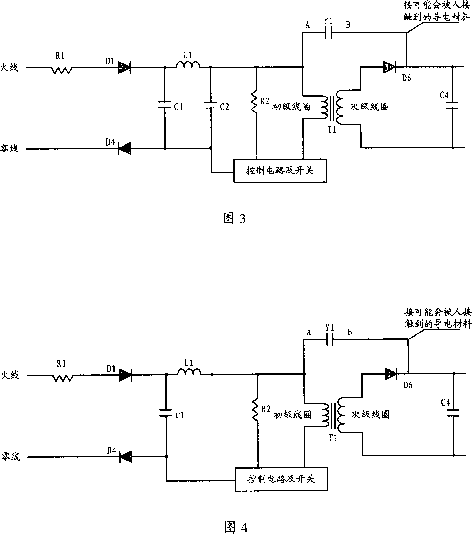
[0019] The first embodiment of the present invention is shown in FIG. 2 . The electronic equipment contains a half-bridge rectifier circuit (composed of D1 and D4), and a capacitor Y1, one end of the capacitor Y1 is directly or indirectly connected to an output end of the half-bridge rectifier circuit, and the other end of the capacitor is connected to the electronic The connection of conductive material on the equipment that may be touched by humans. The input terminals X and Y of the half-bridge rectifier circuit are connected to an AC power supply. The connection referred to in the embodiments of the present invention may be a direct connection or a connection through other circuits, as long as the two devices can conduct on a direct current. Conductive mater...


PUM


Abstract

The disclosed electronic equipment uses half bridge rectification circuit instead of full bridge rectification circuit in current technique. Even if electronic equipment includes some capacitors. One end of capacitor is connected to an output end of a rectification circuit; and the other end is connected to conducting material of electronic equipment possible to be touched by human; then leakage current will not be generated so as to raise user's experience for using electronic equipment.

Description

technical field [0001] The invention relates to the field of electronic technology, in particular to power supply technology. Background technique [0002] Undoubtedly, today is the era of handheld devices, among which mobile phones have the largest market and usage. For wireless devices such as mobile phones, charging is essential to ensure their normal work. There are many ways to charge mobile phones, mainly by switching chargers. The switching charger uses alternating current, and the charger contains a full-bridge rectifier circuit composed of four diodes, as shown in Figure 1. When the charger is connected to an external AC power supply, the input AC power is converted into a higher DC voltage through the full-bridge rectifier circuit and the supporting inductance and capacitance, and then converted into the required low-voltage DC voltage through the transformation of the control circuit, switch and inductance T1. Output for charging the mobile phone. In this circu...

Claims


Application Information

Patent Timeline
IPC IPC(8): H02J7/10H02M7/00H02M3/28
Inventor 刘海龙魏孔刚
Owner HUAWEI TECH CO LTD
Learn More